
Forging Die Design: A Stepwise Approach
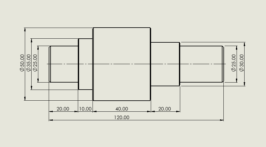
In this blog, I will walk you through the process of designing a forging die for a simple shaft. The goal is to demonstrate the key steps involved in die design, including part modeling, adding machining allowances, and preparing the die features. The drawing of the shaft, which serves as the reference for this design, is shown below for better understanding.
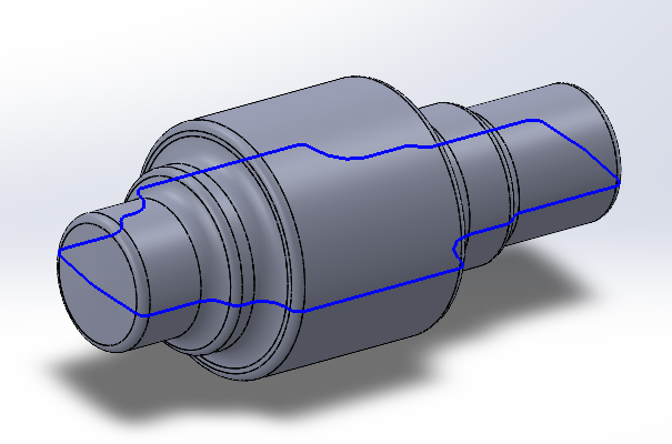
First, we need to create a 3D model of the part. This can be done using any 3D CAD software—I’m personally using SolidWorks. Since our goal is to learn the steps involved in designing a forging die, the specific software isn’t important. What really matters is understanding and following the process.
Creating 3D Model

After creating the initial 3D model of the part, the next crucial step is to add extra material, commonly referred to as machining allowance or machining margin. This additional material is essential because the forged part, as produced by the forging process, typically does not meet the exact surface finish and dimensional specifications required for the final product. Proper forging die design ensures that the rough shape is created accurately while leaving enough material for machining.
Forging shapes the metal roughly to the desired form, but to achieve the precise measurements and smooth surfaces needed, subsequent machining operations are necessary. By including machining margins in the design, we ensure there is sufficient material available to be removed during these finishing processes. This helps prevent any defects or irregularities in the final dimensions, guaranteeing the part functions as intended in its application. Effective forging die design accounts for these machining allowances to optimize the final outcome.
Once the machining margins are added to the initial model, the next step is to adapt this design into a forging-ready part. This conversion is a critical phase because forging imposes specific requirements on part geometry to facilitate manufacturing and avoid defects. At this stage, forging die design principles are applied to add features such as appropriate margins, fillets, and draft angles.
Margins serve as buffer zones to accommodate material flow and machining allowance. Fillets, or rounded edges, are introduced to reduce stress concentrations and improve the flow of material during forging, which minimizes the risk of cracks and other defects. Draft angles are also incorporated into the design, which are slight tapers on the faces of the part that help with the easy removal of the forged component from the die. Without proper draft angles, the part could get stuck inside the forging die, leading to damage or inefficiency in the manufacturing process. These considerations are fundamental aspects of sound forging die design.
The role of forging die design is to ensure the forging process runs smoothly, producing parts that meet design requirements and are easy to manufacture. A well-executed forging die design results in components with improved mechanical properties due to optimized grain flow and reduced defects.
Throughout the process, forging die design focuses on balancing manufacturability and part performance. For example, forging die design must consider how the metal will flow under compressive forces to avoid areas of insufficient fill or excessive flash.
Furthermore, advanced software tools aid in forging die design by simulating metal flow, stress distribution, and potential defect zones, allowing engineers to refine the die geometry before manufacturing. This leads to cost savings and higher quality output.
The integration of machining allowances during forging die design is vital because it ensures that the final machining step can produce parts within tight tolerances. If machining margins are too small or inconsistently applied, it can cause rework or scrap.
Additionally, forging die design must incorporate features that facilitate easy die maintenance and longevity, such as wear-resistant inserts and optimized cooling channels. These elements improve productivity and reduce downtime.
In summary, successful forging die design involves carefully planning for machining allowances, stress relief features like fillets, and draft angles, all tailored to the specific part requirements. This holistic approach ensures the forged part is both manufacturable and high quality.
Understanding and applying proper forging die design principles can significantly reduce defects such as cracks, laps, or incomplete filling, which often arise from poor die geometry.
Ultimately, forging die design is a critical step that bridges the gap between raw forging and final machining, ensuring parts meet stringent industry standards while maintaining efficient production.
Creating Forging Model

The image clearly demonstrates how machining margins are incorporated into the part design. In this example, a 2 mm allowance is added uniformly to each side of the part. This additional material, known as the machining margin or allowance, is essential in the forging process. It provides enough stock for subsequent machining operations, which are necessary to achieve the required surface finish and precise dimensional tolerances. Without these margins, it would be difficult to accurately machine the forged part, potentially resulting in defects or deviations from the design specifications. Adding machining margins ensures better quality and reliability in the final component.

The forging part design is still incomplete as fillets have yet to be added. Incorporating fillets is essential to reduce stress concentrations, improve material flow during forging, and prevent cracking. Once the fillets are properly integrated, the design will be ready for further processing and validation.

The forging part design is now complete and ready to proceed to the next stage of the manufacturing process. This involves preparing the design for die manufacturing, conducting simulations, or moving forward with actual forging operations. Key features such as machining margins, fillets, and draft angles have been carefully incorporated to ensure the part can be forged efficiently and removed from the die without issues. These design considerations help improve material flow, reduce stress concentrations, and guarantee that the final forged part meets the required specifications for quality and performance.

The difference between the machined part and the forging part is quite noticeable—the forging part is significantly larger than the machined component. This size difference is intentional and necessary for the manufacturing process. The extra material added to the forging part is known as the machining allowance or machining margin. Its primary purpose is to provide sufficient stock that can be removed during the subsequent machining operations. Proper forging die design takes this allowance into account to ensure the forged part can be finished accurately.
Forging produces parts that are close to the desired shape but usually lack the precise dimensions and smooth surface finishes required for final use. By incorporating machining allowances, manufacturers ensure there is enough material to machine the part to its exact specifications. This includes achieving the required dimensional accuracy, tight tolerances, and a high-quality surface finish. Effective forging die design balances the need for sufficient machining margin with material efficiency.
Without this extra material, the forged part might not meet the critical standards needed for functionality and fit, potentially leading to defects or failure in service. The machining allowance also compensates for any minor distortions or surface imperfections that can occur during forging. Therefore, adding this margin is an essential step that balances the strengths of forging with the precision of machining to produce a final component that meets both quality and performance requirements. This step is a key consideration in forging die design.
In conclusion, thoughtful forging die design integrates the machining allowance seamlessly, ensuring the forged parts are both manufacturable and ready for precise finishing. Neglecting these design aspects can lead to costly rework or scrap. Hence, the role of forging die design is critical in bridging the gap between raw forging and final machining to achieve optimal part quality.
Scaling the Forging Part

The picture shows how we use the scale option to enlarge the part by 1.5%. This step compensates for the shrinkage that occurs when the forged part cools, ensuring the final dimensions are accurate. Scaling maintains the part’s proportions while adjusting its size for manufacturing requirements, a key consideration in forging die design.
In this step, it is necessary to scale the part, meaning we increase its size beyond the original forging dimensions. Specifically, the part must be enlarged by a scale factor of 1.5%, which means increasing all dimensions of the part by 1.5%. This adjustment is critical because forged parts undergo shrinkage as they cool down after the forging process. The metal contracts during cooling due to thermal contraction, which causes the final part to be smaller than the original forged shape. Accounting for this shrinkage accurately is an important aspect of effective forging die design.
To compensate for this shrinkage and ensure the final dimensions meet the required specifications, the design is scaled up before forging. By increasing the size of the part by 1.5%, we account for the expected reduction in size after cooling, which helps maintain dimensional accuracy. This scaling process must be carefully integrated within the forging die design to avoid costly errors.
Without this scaling step, the finished part could end up undersized, potentially leading to fitment issues, reduced functionality, or the need for costly rework. Proper forging die design anticipates these challenges by incorporating appropriate scale factors based on material type and part geometry.
This scaling process is a standard practice in forging design and manufacturing, requiring precise calculation and experience to predict the correct shrinkage percentage for different materials and part geometries. Incorporating shrinkage compensation into the forging die design ensures the forged part meets specifications after cooling and stabilization.
Moreover, forging die design involves balancing the scaling factor with machining allowances and draft angles to optimize both form and function. This coordination enhances the overall quality of the forged part and streamlines production.
Proper scaling helps ensure that once the forged part cools and stabilizes, it will closely match the intended design dimensions, leading to better performance and reduced material waste. The ability to accurately predict and apply scaling in forging die design is essential to producing high-quality forged components reliably.
In summary, forging die design plays a pivotal role in managing dimensional changes due to shrinkage through careful scaling, thereby guaranteeing that the final forged parts conform precisely to their design requirements.
In this step, we create the lock feature in the forging die to control and prevent mismatch during the forging process. Mismatch occurs when the two halves of the die do not align perfectly, which can lead to defects in the forged part. The lock helps ensure precise alignment by mechanically interlocking the die halves, maintaining correct positioning throughout forging. This improves the quality and consistency of the final part, reduces flash formation caused by misalignment, and protects the die from damage. Incorporating locks is essential for achieving accurate and reliable forging results.
Creating Parting Line
The next important step in the forging design process is to create the parting line. The parting line defines where the forging die will open and separate during the manufacturing process. It is a crucial feature because it determines how the two halves of the die come together and how the forged part is formed and removed. Proper placement of the parting line ensures that the die can open smoothly without damaging the part or the tooling.
Creating the parting line involves careful analysis of the part’s geometry to identify the most suitable location for die separation. This line typically follows natural divisions in the part’s shape, allowing for easy removal after forging. If the parting line is not correctly positioned, it could lead to defects such as flash (excess material), difficulty in part removal, or damage to the die.
The design software offers tools to accurately define and visualize the parting line. By marking this line, engineers can prepare the die layout and ensure that the forging process will be efficient and defect-free. Ultimately, the creation of the parting line is essential for successful forging, as it affects both the quality of the final part and the longevity of the die.
Die Creation
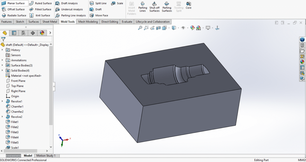
At this stage, we have created the impression of the part into the forging die. To achieve this, I am using the “Tooling Split” feature available in SolidWorks, which is a powerful tool designed specifically for mold and die design. This function allows us to divide the die into separate sections based on the geometry of the part. Before using Tooling Split, I first generate the parting surface by utilizing the “Parting Surfaces” option, which is found in the Mold Tools section of SolidWorks. The parting surface defines where the die will separate or open, serving as a critical boundary between the two halves of the die.
Creating an accurate parting surface is essential, as it ensures the die halves fit together precisely and that the forged part can be properly formed and removed without damage. Once the parting surface is established, the Tooling Split command uses this surface to automatically split the die into the required sections. This process significantly streamlines die design by accurately producing the core and cavity of the die based on the 3D model of the part.
Using these SolidWorks tools not only increases efficiency but also improves accuracy in the die manufacturing process. It helps prevent errors that could arise from manual splitting, ensuring a better fit and functionality of the forging die. This method ultimately leads to higher quality forged parts and extends the lifespan of the tooling.
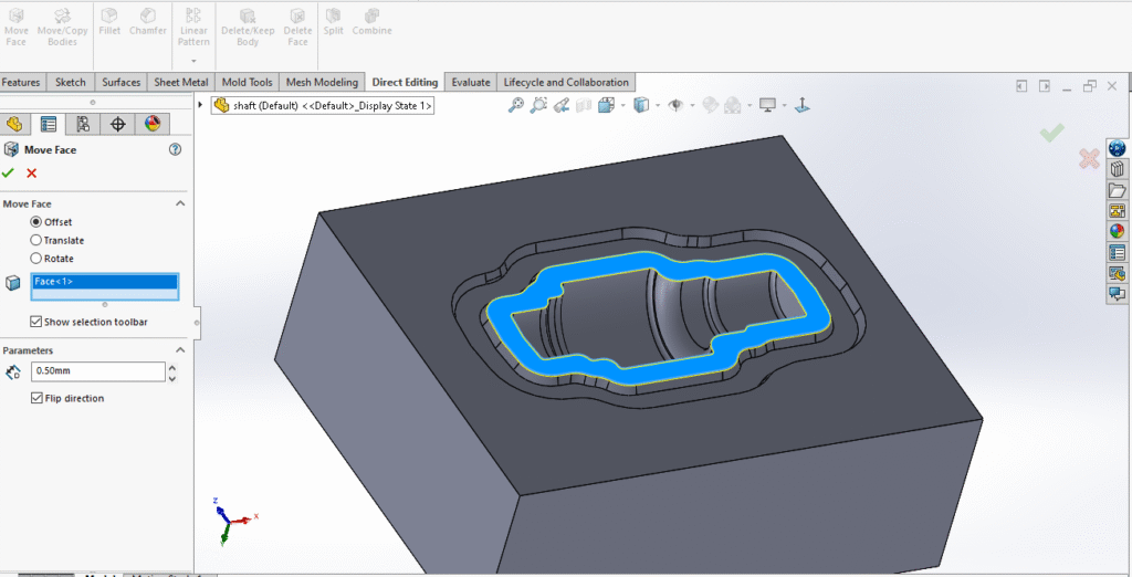
After creating the die impression and splitting the tooling, the next step is to design the flash and gutter features in the die. Flash refers to the thin excess material that flows out between the die halves during forging, while the gutter is a channel designed to collect and direct this excess material away from the part. Adding a properly sized flash and gutter is essential to allow the surplus metal to escape during the forging process, preventing defects and ensuring the final part maintains its intended shape. This also helps protect the die from damage caused by trapped material.
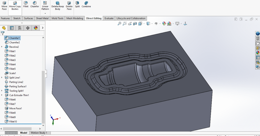
Next, fillets are added to all sharp edges and corners within the die design. Incorporating fillets helps improve the flow of material during the forging process by reducing stress concentrations and allowing the metal to move smoothly around corners. This prevents potential cracking or defects caused by abrupt changes in geometry and ensures a more uniform filling of the die cavity. Additionally, fillets extend the life of the die by minimizing wear and reducing the risk of damage at sharp points, ultimately leading to higher quality forged parts and more efficient manufacturing.

The die impression, along with the flash and gutter areas, is clearly highlighted in red in the image. Notably, there is a small gap between the flash areas, which plays a crucial role in allowing excess material to flow smoothly into the gutter during forging. This gap ensures that the surplus metal is properly channeled away from the part, preventing defects and ensuring the final product’s dimensional accuracy. Proper design of this gap is essential for efficient material flow, reducing the risk of die damage and improving the overall quality of the forged component.
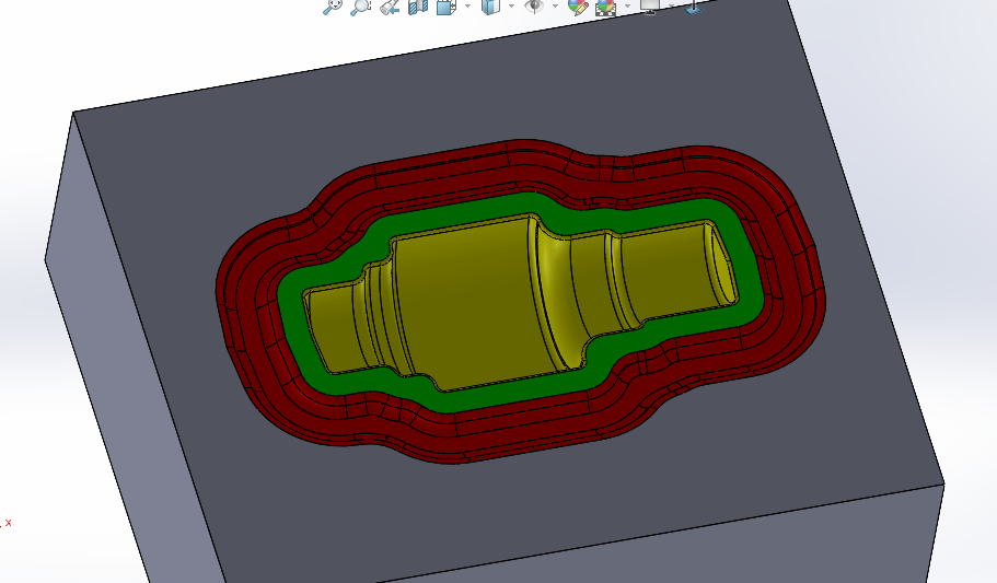
In this image, I have highlighted three distinct areas using different colors to make the design easier to understand. The yellow-colored area represents the part impression, which is the exact shape that the forged part will take. The green area indicates the flash area, while the red area shows the gutter. Each of these zones plays a vital role in the forging process and the overall forging die design.
During the forging process, the raw material is placed into the die and subjected to high pressure, causing it to change shape and fill the cavity of the die. The yellow area, or the part impression, defines the final form of the forged component. This is where the metal must flow precisely to replicate the desired geometry and dimensions of the part—a critical focus in effective forging die design.
However, as the material is compressed, excess metal is forced out of the die cavity. This surplus material flows into the flash area, highlighted in green. The flash acts as an overflow region, allowing the extra material to escape from the main part cavity. Proper consideration of the flash area is an important aspect of forging die design to prevent defects.
The flash material is then directed into the gutter, shown in red, which collects and channels the excess metal away from the die. The gutter helps keep the forging clean and prevents the excess metal from interfering with the die operation, making it an essential feature in forging die design.
Both the flash and gutter areas are essential features in forging die design. They ensure proper material flow, protect the die from damage, and contribute to producing high-quality forged parts. Careful planning of these areas is vital during the forging die design phase.
By clearly differentiating these areas in the design, engineers can better analyze and optimize the forging process for efficiency and quality. Such differentiation is a core principle in advanced forging die design practices.
The success of a forging operation heavily depends on how well the forging die design manages material flow between the part impression, flash, and gutter. Optimizing these elements reduces waste and improves part consistency.
In summary, a well-executed forging die design carefully integrates the part impression, flash, and gutter areas to enhance performance, extend die life, and ensure the production of defect-free forged components.
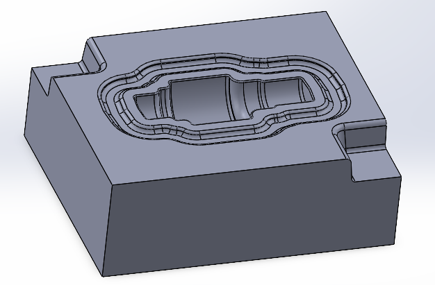
In this step, we create the lock feature in the forging die to control and prevent mismatch during the forging process. Mismatch occurs when the two halves of the die do not align perfectly, which can lead to defects in the forged part. The lock helps ensure precise alignment by mechanically interlocking the die halves, maintaining correct positioning throughout forging. This improves the quality and consistency of the final part, reduces flash formation caused by misalignment, and protects the die from damage. Incorporating locks is essential for achieving accurate and reliable forging results.
In summary, the design of a forging die plays a pivotal role in the success of the forging process and the quality of the final product. A well-crafted die ensures that the raw material flows correctly to fill the die cavity, forming a part that closely matches the desired specifications. Key design elements such as machining allowances, parting lines, flash and gutter areas, fillets, and locking features must be carefully integrated to optimize the forging operation.
Machining allowances provide extra material for finishing, ensuring accurate dimensions and surface finishes after forging. The parting line defines where the die splits, enabling smooth opening and closing while preventing damage. Flash and gutter areas manage excess material flow, protecting the die and maintaining part quality. Fillets reduce stress concentrations, improving material flow and die life, while locks prevent die mismatch, ensuring precise alignment.
Attention to these details minimizes defects, reduces wear and tear on the die, and enhances production efficiency. Ultimately, forging die design requires a balance between engineering principles and practical manufacturing considerations. Investing time and expertise in die design leads to consistent, high-quality forged parts, reduced production costs, and longer tool life, making it an essential foundation for any successful forging operation.

