Infohub01.com

Engineering Processes

rolling

Rolling in Metal Forming: 7 Powerful Benefits You Should Know

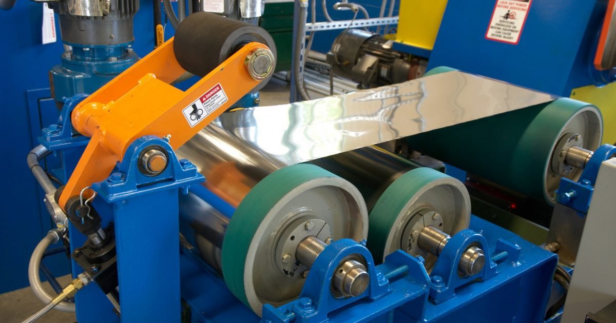
What is Rolling Rolling is a metal forming process in which metal stock is passed through one or more pairs of rotating rolls to reduce its thickness, improve uniformity, and enhance mechanical properties. It is commonly used to produce sheets, plates, bars, and other structural forms. Rolling can be performed at high temperatures (hot rolling) or room temperature (cold rolling), each offering specific benefits. Hot rolling improves workability, while cold rolling enhances surface finish and strength. Rolling is highly efficient, cost-effective, and widely used in industries such as construction, automotive, and manufacturing to produce precise and consistent metal products at scale. Types of Rolling Processes 1. Based on Temperature    a. Hot Rolling    b. Cold Rolling 2. Based on Direction of Roll Movement    a. Forward (or Direct) Rolling    b. Reverse Rolling    c. Cross Rolling    d. Transverse Rolling 3. Based on Number of Rolls in the Mill    a. Two-High Rolling Mill    b. Three-High Rolling Mill    c. Four-High Rolling Mill    d. Cluster (Sendzimir) Mill    e. Planetary Rolling Mill 4. Based on Product Form    a. Flat Rolling    b. Shape Rolling (Profile Rolling)    c. Ring Rolling 5. Specialized Rolling Processes    a. Thread Rolling    b. Roll Bending    c. Skew Rolling 1. Based on Temperature Hot Rolling Hot rolling is a metalworking process in which metal is heated above its recrystallization temperature and then passed through rollers to reduce its thickness and shape it into the desired form. This process is commonly used in the production of large sections such as sheets, plates, and structural components like beams and rails. Heating the metal above its recrystallization temperature—typically above 900°C for steel—makes it more malleable and easier to deform without cracking. The material is initially cast into large slabs or billets, then reheated in a furnace, and finally passed through a series of rolling mills. As the metal moves through the rollers, its grain structure refines, enhancing mechanical properties like toughness and ductility. Hot rolling is efficient and cost-effective for shaping large volumes of metal. However, it may result in surface scaling and lower dimensional accuracy compared to cold rolling. Despite this, hot-rolled products are widely used in construction, automotive, and industrial applications due to their strength and formability. The process concludes with cooling the rolled material, which is then cut and shaped into final products or stored as coils or bars for further processing. Overall, hot rolling is a fundamental process in the modern steel and metal industry. Cold Rolling Cold rolling is a metalworking process in which metal is passed through rollers at room temperature, below its recrystallization point. Unlike hot rolling, cold rolling does not involve heating the metal before shaping, which allows for greater precision and improved surface finish. This process is typically used to produce thin sheets, strips, and high-precision metal parts. During cold rolling, the metal is first hot-rolled and pickled to remove scale, then passed through rollers to reduce thickness and improve surface characteristics. Because the material is processed at lower temperatures, it hardens through strain hardening, which increases its strength and hardness but may reduce ductility. Cold rolling results in closer dimensional tolerances, a smoother surface finish, and enhanced mechanical properties compared to hot rolling. These advantages make cold-rolled steel ideal for applications requiring tight tolerances and high-quality finishes, such as in automotive panels, appliances, and precision components. However, due to the increased hardness from cold working, additional annealing processes may be required to restore ductility if further shaping is needed. Overall, cold rolling is a vital process in producing high-quality, precision metal products for advanced manufacturing and engineering applications. 2. Based on Direction of Roll Movement Forward (or Direct) Rolling Forward (or Direct) Rolling is a fundamental metal forming process in which the workpiece and the rolls move in the same direction. This technique is commonly used in hot and cold rolling operations to reduce the thickness of metal stock and shape it into desired profiles. In forward rolling, the metal strip is fed into the rotating rolls, which apply compressive forces as it passes through the roll gap. The rolls rotate in opposite directions, pulling the material forward due to friction and simultaneously reducing its cross-sectional area. The direction of the strip’s movement aligns with the rotation of the roll surfaces in contact with the material, ensuring a smooth and continuous deformation process. This method is efficient and widely used for producing sheets, plates, and various long products such as rods and bars. Forward rolling offers advantages like high production rates, uniform thickness, and the ability to process large volumes of metal. However, precise control of roll speed and temperature is essential to maintain product quality. This process is essential in industries such as construction, automotive, and manufacturing, where consistent and reliable metal shapes are required. Reverse Rolling Reverse Rolling is a metal forming process where the direction of rolling is alternated after each pass through the rollers. Unlike forward rolling, in reverse rolling, the workpiece is passed back and forth through the same set of rolls, with the roll rotation direction reversed each time. This method is commonly used in both hot and cold rolling processes, especially when dealing with small batches or when precise thickness control is required. During reverse rolling, the metal strip is passed through the rollers in one direction, then the rolls are reversed, and the strip is fed back through. This cycle is repeated until the desired thickness or shape is achieved. The main advantage of reverse rolling is that it requires only one set of rolls and can produce high-precision products without needing multiple rolling stands. Reverse rolling is particularly suitable for rolling thick plates, specialty alloys, and small production runs. Although it is slower than continuous forward rolling, it allows for better control over material properties, such as thickness and flatness. Industries like aerospace, defense, and high-performance manufacturing often use reverse rolling for producing custom or high-specification metal components. Cross Rolling Cross

Rolling in Metal Forming: 7 Powerful Benefits You Should Know Read Post »

Mechanical Properties

13 Essential Mechanical Properties of Materials Explained

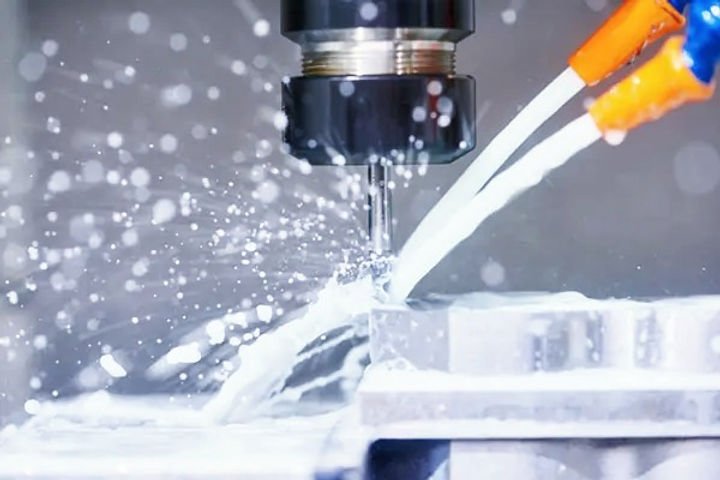
Cutting Fluids in Machining – Types and Their 5 Critical Roles in Boosting Machining Quality5 Essential Machining Tolerances – What They Are and Why They MatterGD&T – The Basics of Geometric Dimensioning and Tolerancing, 5 Efficient & Reliable MethodsG-code and M-code Commands for CNC Beginners : 5 Essential & Effective TipsDiscover Mechanical Processes Explained: 7 Essential Techniques Every Engineer Must Know What Are Mechanical Properties of Materials? Mechanical properties refer to the behaviors and responses of materials when subjected to mechanical forces such as tension, compression, shear, bending, or torsion. These properties describe how a material will react when loaded—whether it will stretch, compress, bend, break, or remain stable. Understanding these properties is crucial for engineers, designers, and manufacturers to select the right materials for specific applications and ensure safety, durability, and performance. Key Mechanical Properties of Materials Materials are the building blocks of engineering and manufacturing, and understanding their mechanical properties is essential for designing safe, efficient, and durable products and structures. Mechanical properties describe how materials respond to various forces and loads, determining their suitability for different applications. Below, we explore the key mechanical properties in depth. 1. Strength : Strength is one of the most fundamental mechanical properties. It describes the ability of a material to resist deformation and failure under applied forces or loads. When engineers design structures or components, they must ensure the materials used can withstand the expected forces without breaking or deforming excessively. Types of Strength Tensile StrengthTensile strength is the resistance of a material to breaking under tension, i.e., being pulled apart. This is one of the most common ways to test strength, involving gripping a specimen at both ends and pulling it until it fractures. The maximum stress the material withstands in this process is its tensile strength. For example, steel wires used in suspension bridges are chosen because of their high tensile strength. Compressive StrengthCompressive strength measures a material’s ability to resist forces that try to squash or compress it. Materials like concrete and stone are known for their high compressive strength, which is why they are widely used in foundations and columns that bear heavy loads pushing downward. Shear StrengthShear strength is the resistance to forces that cause different parts of a material to slide past each other in opposite directions. Imagine scissors cutting paper—that cutting action applies shear stress to the paper. Shear strength is crucial in applications such as rivets and bolts, which must resist sliding forces. Importance of Strength Knowing a material’s strength helps in selecting appropriate materials for various structural and mechanical uses. For example, aircraft wings experience tremendous tensile, compressive, and shear forces during flight, so materials with high strength in all three forms are essential. 2. Elasticity Elasticity is the property that allows a material to return to its original shape and size after the removal of the applied force that caused deformation. When a load is applied within the elastic limit of the material, deformation is temporary and reversible. This is analogous to stretching a rubber band and letting it snap back. Elastic Limit The elastic limit is the maximum stress a material can endure without experiencing permanent deformation. If stress exceeds this limit, the material undergoes plastic deformation and does not return to its original shape. Hooke’s Law Elastic behavior often follows Hooke’s Law, which states that the stress applied to a material is directly proportional to the strain (deformation) it causes, up to the elastic limit. This linear relationship allows engineers to calculate how materials will behave under small loads. Applications of Elasticity Elasticity is critical for components like springs, which must deform under load but return to their original shape to perform repeatedly. Also, understanding elasticity helps predict how much a structure might deform under load, which is vital in buildings and bridges. 3. Plasticity Plasticity is the opposite of elasticity in a sense—it is the ability of a material to undergo permanent deformation without breaking once the elastic limit is exceeded. When a material behaves plastically, the atoms within it rearrange irreversibly, and the material keeps its new shape even when the load is removed. Plastic Deformation Unlike elastic deformation, plastic deformation is permanent. Metals such as copper and aluminum exhibit significant plasticity, which allows them to be shaped by forging, rolling, or extrusion without cracking. Importance of Plasticity Plasticity is crucial in manufacturing processes that involve shaping metals and polymers. For instance, car body panels are often shaped through plastic deformation. Additionally, plasticity allows materials to absorb energy during impact, reducing the chance of brittle failure. 4. Ductility Ductility is a measure of how much a material can be plastically deformed (stretched or drawn) before it fractures. A highly ductile material can be stretched into thin wires or bent significantly without breaking. Measuring Ductility Ductility is commonly measured by elongation (percentage increase in length before fracture) or reduction in area during a tensile test. Materials with elongation values above 10% are generally considered ductile. Examples of Ductile Materials Metals such as copper, aluminum, gold, and mild steel are known for their ductility. Copper wires used in electrical cables are a classic example of ductile materials being stretched into thin, flexible forms. Why Ductility Matters Ductility is important in applications where materials must withstand deformation during manufacturing or use. It also provides warning before failure: ductile materials tend to deform visibly before breaking, giving engineers time to detect problems. 5. Malleability Malleability is the ability of a material to deform plastically under compressive stress, such as being hammered or rolled into thin sheets, without cracking or breaking. It reflects how well a material can be shaped by compressive forces. Measuring Malleability Malleability is often assessed by how thin a metal can be hammered or rolled without fracturing. Compression tests or practical forming processes like rolling sheets help evaluate it. Examples of Malleable Materials Metals such as gold, silver, copper, and aluminum are highly malleable. For example, gold can be hammered into extremely thin sheets known as gold

13 Essential Mechanical Properties of Materials Explained Read Post »

Mechanical Processes

Discover Mechanical Processes Explained: 7 Essential Techniques Every Engineer Must Know

What Are Mechanical Processes? Mechanical processes involve the application of physical forces or actions to alter the shape, size, or physical properties of a material without changing its chemical composition. These methods are essential in various fields, including mechanical engineering, manufacturing, and materials science. Common mechanical processes include cutting, grinding, milling, drilling, forging, rolling, and extrusion, each serving a specific function in modifying materials for practical use. These processes enable raw materials—such as metals, polymers, and composites—to be transformed into usable components or finished products with desired specifications. Mechanical processing not only enhances the usability of a material but also improves its mechanical performance, such as strength, hardness, and durability. In industrial settings, the choice of mechanical process depends on factors such as material type, desired outcome, cost-effectiveness, and production scale. Overall, mechanical processes play a critical role in modern production systems, supporting innovation, efficiency, and the development of high-performance materials and products. Types of Mechanical Processes: Machining Processes Forming Processes Shearing and Cutting Processes Joining and Assembly Processes Finishing and Surface Treatment Processes Material Shaping and Consolidation Recycling and Reduction Processes Machining Processes Machining processes are manufacturing methods used to remove material from a workpiece to shape it into the desired form. These processes include turning, milling, drilling, and grinding, each providing precise control over size, shape, and surface finish. Machining is essential in industries like aerospace, automotive, and medical device production due to its ability to produce accurate and high-quality components. With advancements like CNC (Computer Numerical Control), machining has become more efficient, automated, and capable of achieving tight tolerances and complex geometries. Types of Machining Processes Turning  Milling Drilling Boring Reaming Tapping Broaching Sawing Grinding Honing Lapping EDM (Electrical Discharge Machining)  Importance of Machining Processes Precision and AccuracyMachining allows for very precise shaping and finishing of materials, often to exact specifications, which is crucial for manufacturing high-quality parts. VersatilityIt can be applied to a wide range of materials including metals, plastics, and composites, enabling the creation of diverse components. Surface FinishMachining processes can produce smooth and fine surface finishes, improving the performance and appearance of the product. CustomizationIt enables custom or low-volume production of parts with complex geometries that might not be possible through casting or forging. Material UtilizationMachining removes only the necessary material, which can minimize waste compared to other manufacturing methods. Repair and ModificationIt allows for the repair or modification of existing parts, extending their useful life. Tool and Die MakingEssential for producing the precise tools and dies used in mass production processes. Applications of Machining Processes Automotive IndustryProduction of engine components, transmission parts, gears, shafts, and other precision parts. Aerospace IndustryManufacturing of high-tolerance aircraft components such as turbine blades, structural parts, and landing gear. Medical DevicesCreation of surgical instruments, implants, and prosthetics requiring high accuracy and biocompatibility. ElectronicsMachining of small, precise components for devices and housings. Tool and Die IndustryMaking molds, dies, jigs, and fixtures used in other manufacturing processes. Defense and MilitaryProduction of weapons, ammunition components, and other defense equipment parts. General ManufacturingProducing parts for machinery, equipment, consumer goods, and more. Advantages of Machining Processes High Precision and Accuracy Can produce parts with very tight tolerances and exact dimensions. Good Surface Finish Produces smooth surfaces, often requiring little or no further finishing. Versatility Applicable to a wide variety of materials, shapes, and sizes. Flexibility for Complex Shapes Can create intricate and detailed parts that may be difficult to form by other means. Quick Setup for Small Production Runs Ideal for prototypes, custom parts, and small batches without expensive tooling. Repair and Modification Enables easy repair or alteration of existing parts. Limitations of Machining Processes Material Waste : Removes material in the form of chips, which can be inefficient and costly for expensive materials. High Energy Consumption : Machining often requires significant power, especially for hard materials. Tool Wear and Maintenance : Cutting tools wear out and need regular replacement or sharpening. Slower for Large Production Runs : Less efficient than casting or forging for mass production due to slower material removal rates. Size Limitations : Limited by the size of the machine and tooling; very large parts may be difficult to machine. Heat Generation : Produces heat during cutting, which can affect material properties and tool life if not properly managed. Forming Processes Forming processes involve shaping materials, usually metals or plastics, by applying force without removing material. Common techniques include forging, rolling, extrusion, and sheet metal bending. These processes change the shape and size of a workpiece by deforming it plastically, improving strength and structural properties. Forming is widely used in manufacturing industries to produce parts like automotive components, pipes, and structural elements. It is efficient and cost-effective for mass production, often producing parts with excellent mechanical properties and minimal waste. Types of Forming Processes Forging (hot and cold) Rolling (hot and cold) Extrusion Drawing Sheet Metal Forming Stamping Hydroforming Importance of Forming Processes Efficient Material Usage : No material is removed, so there is minimal waste, making it cost-effective, especially for expensive materials. Improved Mechanical Properties : The deformation during forming often enhances strength and toughness through strain hardening and grain refinement. High Production Rates : Many forming processes are suitable for mass production with fast cycle times. Complex Shapes : Enables the production of complex and near-net shapes that reduce the need for further machining. Versatility : Can be applied to a wide range of materials and product sizes, from small parts to large structural components. Applications of Forming Processes Automotive Industry : Manufacturing of body panels, crankshafts, gears, and axles. Aerospace : Production of aircraft frames, turbine blades, and other structural parts. Construction : Creation of beams, pipes, rods, and reinforcement bars. Consumer Goods : Manufacture of household appliances, utensils, and hardware. Industrial Machinery : Components like shafts, rollers, and bearings. Advantages of Forming Processes Minimal Material Waste : Since no cutting is involved, raw material usage is optimized. Enhanced Strength and Durability : Cold forming improves mechanical properties through work hardening. Cost-Effective for Large Quantities : Ideal

Discover Mechanical Processes Explained: 7 Essential Techniques Every Engineer Must Know Read Post »

Geometric Dimensioning and Tolerancing

GD&T – The Basics of Geometric Dimensioning and Tolerancing, 5 Efficient & Reliable Methods

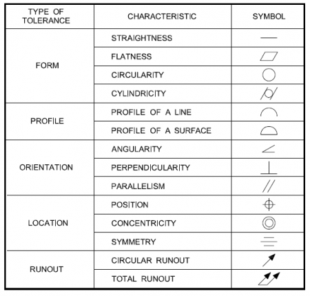
Advanced Machining & Automation: 5 Exciting Industry Trends to Watch10 Best Materials Used in Machining: A Complete Guide for ManufacturersHow to Read Machining Drawings: 11 Essential Tips for BeginnerCutting Fluids in Machining – Types and Their 5 Critical Roles in Boosting Machining Quality5 Essential Machining Tolerances – What They Are and Why They Matter What is GD&T? GD&T stands for Geometric Dimensioning and Tolerancing. It is a symbolic language used in engineering and manufacturing to precisely communicate the geometry and allowable variation (tolerances) of parts and assemblies. Key Concepts in GD&T: Geometric Tolerances: GD&T defines tolerances for form, orientation, location, and runout. These tolerances control the allowable variation in the shape and position of features on a part. Feature Control Frames: These are rectangular boxes containing GD&T symbols, tolerance values, and datums that clearly communicate how much variation is allowed. Datums: Reference points, lines, or surfaces on a part used to establish a coordinate system for measurement. Symbols: GD&T uses standardized symbols (from ASME Y14.5 or ISO standards) to represent tolerances, such as: Straightness (─) Flatness (⏥) Circularity (○) Cylindricity (⌭) Perpendicularity (⊥) Parallelism (∥) Position (⭘) Concentricity (◎) Symmetry (⌯) Advantages of GD&T: Improves communication between design, manufacturing, and inspection. Reduces ambiguity compared to traditional dimensioning. Allows for more cost-effective manufacturing by clarifying what is functionally important. Example: Imagine a hole in a plate. Instead of just giving its location and diameter with simple linear tolerances, GD&T can define: The hole’s position tolerance relative to a coordinate system defined by datums. Its cylindricity tolerance to control roundness and straightness along its axis. Its perpendicularity to the surface. This ensures the part functions as intended while allowing flexibility in manufacturing. Why Implement GD&T Processes? Great question! Implementing GD&T processes in design and manufacturing offers a bunch of important benefits that improve product quality, communication, and cost-efficiency. Here’s why companies and engineers choose to use GD&T: 1. Clear Communication of Design Intent GD&T provides a standardized language that precisely defines allowable variation in part features. This removes ambiguity compared to traditional dimensioning, reducing misinterpretations between design, manufacturing, and inspection teams. 2. Better Control Over Part Functionality GD&T focuses on the function of a part rather than just its size. By controlling geometric relationships (like flatness, perpendicularity, position), parts are more likely to assemble and function correctly, even if some dimensions vary within tolerances. 3. Improved Quality and Consistency Using GD&T helps ensure parts meet critical requirements, reducing defects and rework. Inspection becomes more straightforward and repeatable with clear tolerance zones tied to functional requirements. 4. Cost Savings GD&T allows for functional tolerances instead of overly tight, uniform tolerances. This flexibility can reduce manufacturing costs by allowing looser tolerances where acceptable without sacrificing quality. It also decreases scrap rates and rework. 5. Simplified Inspection and Measurement GD&T clearly defines how and where to measure features, speeding up inspection processes. Using datums and feature control frames standardizes measurement setups. 6. Supports Advanced Manufacturing Techniques GD&T is essential for precision manufacturing methods, like CNC machining, 3D printing, and automated inspection. It enables the use of coordinate measuring machines (CMMs) and software to verify complex geometries effectively. 7. Improved Interchangeability and Assembly Ensures parts fit together properly even if manufactured by different suppliers. Critical for large assemblies where multiple parts must interface precisely. How GD&T Works Defining the Part Geometry with Symbols Instead of only specifying linear dimensions (like lengths or diameters), GD&T uses a set of standardized symbols to describe the form, orientation, location, and runout of features on a part. These symbols communicate what kind of geometric control is required. Using Feature Control Frames GD&T specifies tolerances in feature control frames—these are rectangular boxes attached to the drawing near a feature. A feature control frame contains: The GD&T symbol (e.g., position, flatness) The tolerance value (how much deviation is allowed) Reference to datums (if applicable), which are the theoretical exact points or surfaces used as references for measurements Establishing Datums Datums serve as the “origin” or reference for measuring part features. GD&T sets up a coordinate system on the part using these datums, helping to define how features should be oriented or located relative to each other. Tolerance Zones GD&T defines tolerance zones where the feature must lie to be acceptable. For example: A position tolerance creates a cylindrical zone within which the center of a hole must lie. A flatness tolerance creates a zone between two parallel planes where a surface must lie. Applying Functional Requirements The tolerances set by GD&T are based on functional requirements—what the part needs to do, not just how big or small it should be. This makes sure the part works correctly in its assembly or operation. Measuring and Inspecting During inspection, the part is measured relative to the datums, and the measurements are compared to the tolerance zones specified by the GD&T. This helps ensure the part meets the required geometric standards. Example in Practice: Say you have a hole that must fit a pin tightly but still allow assembly: Instead of just specifying a diameter tolerance, GD&T might specify a position tolerance with reference to the part’s edges (datums). This controls not only the size but where the hole is located relative to the rest of the part, ensuring the pin fits properly. GD&T Symbols Form Controls Flatness : This controls how flat a surface must be. The surface must lie between two parallel planes spaced apart by the tolerance value. It ensures no bumps or dips exceed the allowed flatness. Straightness : Straightness controls how much a line or surface can deviate from a perfectly straight line. For example, the edge of a part or the axis of a cylindrical feature must be within a narrow straightness zone. Circularity or Roundness: This ensures that any cross-section of a round feature (like a hole or shaft) is perfectly circular within a given tolerance. It prevents out-of-round conditions. Cylindricity : A 3D form control that ensures a cylindrical feature is both round and straight along

GD&T – The Basics of Geometric Dimensioning and Tolerancing, 5 Efficient & Reliable Methods Read Post »

Machining Tolerances

5 Essential Machining Tolerances – What They Are and Why They Matter

8 Common Mistakes in Machining and How to Avoid ThemAdvanced Machining & Automation: 5 Exciting Industry Trends to Watch10 Best Materials Used in Machining: A Complete Guide for ManufacturersHow to Read Machining Drawings: 11 Essential Tips for BeginnerCutting Fluids in Machining – Types and Their 5 Critical Roles in Boosting Machining Quality Introduction to Machining Tolerances Machining tolerances are the specified limits of allowable variation in the dimensions of manufactured parts. No matter how precise a machine is, some variation is inevitable during production. Tolerances define the acceptable range within which these variations can occur without compromising the part’s fit, function, or performance. They are fundamental in ensuring that parts can be reliably produced, assembled, and operated in various engineering and manufacturing applications. Without clearly defined tolerances, components may fail to meet design requirements, leading to poor performance, increased costs, or safety issues. What Are Machining Tolerances? Machining tolerances define the permissible range of variation in the physical dimensions of manufactured parts. These tolerances indicate how much a particular measurement can differ from its nominal, or ideal, value while still ensuring that the part functions correctly within its intended application. In essence, tolerances set the boundaries within which a part is considered acceptable, balancing manufacturing feasibility with functional requirements. For instance, consider a shaft designed to have a diameter of 10 millimeters. If the tolerance specified is ±0.05 millimeters, this means the shaft’s diameter can vary between 9.95 mm and 10.05 mm and still be deemed acceptable. The part must fall within this range to fit properly with mating components or to perform its intended mechanical function without causing issues such as excessive wear, poor fit, or mechanical failure. Tolerances are critical in manufacturing because no process can produce parts with perfect accuracy every time. Material properties, machine precision, and environmental factors all influence the final dimensions. Therefore, specifying tolerances helps manufacturers maintain quality and functionality without requiring impossible precision. The tighter the tolerance, the more precise the manufacturing process must be, often increasing production costs and time. Conversely, looser tolerances allow for easier manufacturing but may reduce performance or interchangeability. Types of Tolerances Tolerances are essential in machining and manufacturing as they define the permissible variation in a part’s dimensions. Due to limitations in machine precision and material behavior, it is rarely possible to produce parts at an exact nominal size. Therefore, tolerances ensure that even with slight variations, the part will still fit, function, and perform as intended. There are three primary types of tolerances used in engineering and manufacturing: unilateral, bilateral, and limit tolerances. 1. Unilateral Tolerance In unilateral tolerance, the variation from the nominal dimension is allowed in only one direction—either positive or negative, but not both. This means the actual size of the part can either be larger or smaller than the nominal value, but not both ways. Example: A shaft with a nominal size of 25.00 mm and a tolerance of +0.10/-0.00 mm allows the actual size to range from 25.00 mm to 25.10 mm. Applications: This type of tolerance is used when the part must not exceed a specific dimension, such as fitting into a hole or preventing interference in assemblies. 2. Bilateral Tolerance Bilateral tolerance allows variation in both directions from the nominal size. The tolerance may be equal or unequal above and below the nominal dimension. Example: A part specified as 40.00 mm ±0.05 mm can be manufactured anywhere between 39.95 mm and 40.05 mm. Applications: Bilateral tolerances are commonly used in general machining practices where symmetry of allowable deviation is preferred and where slight deviations in either direction do not critically affect function. 3. Limit Tolerance Limit tolerances specify the maximum and minimum permissible sizes directly, without stating the nominal dimension separately. This provides a clear range within which the actual dimension must fall. Example: A hole specified with limits of 10.00 mm and 10.20 mm indicates that the diameter must be between these two values. Applications: Often used in technical drawings and quality control to simplify inspection and avoid ambiguity during manufacturing. Each type of tolerance serves a specific role depending on design requirements, functional constraints, and manufacturing capabilities. Choosing the right tolerance type helps balance precision, cost, and performance, ensuring that parts can be produced efficiently while still meeting quality standards. Why Do Tolerances Matter? Tolerances play a crucial role in engineering and manufacturing by defining acceptable variations in part dimensions. They ensure that components function as intended, are safe to use, and can be produced efficiently. Here are the key reasons why tolerances are so important: 1. Functionality and FitMany mechanical parts must fit together precisely to work properly. For example, a shaft must fit snugly into a bearing for smooth rotation without excessive play or friction. If the dimensions of either part are outside their specified tolerances, they may not fit correctly, leading to performance issues, wear, or mechanical failure. 2. InterchangeabilityTolerances ensure that parts can be produced consistently, even across different production runs or suppliers. This interchangeability means that components don’t need custom fitting and can be replaced or assembled with minimal variation. It’s especially vital in mass production, where maintaining uniformity saves time and labor. 3. Quality ControlTolerances provide clear, measurable criteria to assess whether a part meets design specifications. This allows for effective inspection during and after manufacturing. By comparing actual measurements to tolerance limits, manufacturers can detect and reject out-of-spec parts early, reducing waste and improving overall quality. 4. Cost EfficiencyTighter tolerances often require more advanced machining techniques, better tooling, and more thorough inspections, all of which increase production costs. By specifying tolerances that are only as tight as necessary for the part to function correctly, designers can reduce manufacturing time and cost without compromising quality or performance. 5. Safety and ReliabilityIn high-risk industries such as aerospace, automotive, or medical devices, precision is critical. Parts that deviate from tolerances can cause system failures, injuries, or worse. Strict adherence to tolerances ensures that critical components perform reliably under demanding conditions, protecting both

5 Essential Machining Tolerances – What They Are and Why They Matter Read Post »

Scroll to Top