Infohub01.com

Machining

Geometric Dimensioning and Tolerancing

GD&T – The Basics of Geometric Dimensioning and Tolerancing, 5 Efficient & Reliable Methods

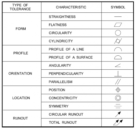
Advanced Machining & Automation: 5 Exciting Industry Trends to Watch10 Best Materials Used in Machining: A Complete Guide for ManufacturersHow to Read Machining Drawings: 11 Essential Tips for BeginnerCutting Fluids in Machining – Types and Their 5 Critical Roles in Boosting Machining Quality5 Essential Machining Tolerances – What They Are and Why They Matter What is GD&T? GD&T stands for Geometric Dimensioning and Tolerancing. It is a symbolic language used in engineering and manufacturing to precisely communicate the geometry and allowable variation (tolerances) of parts and assemblies. Key Concepts in GD&T: Geometric Tolerances: GD&T defines tolerances for form, orientation, location, and runout. These tolerances control the allowable variation in the shape and position of features on a part. Feature Control Frames: These are rectangular boxes containing GD&T symbols, tolerance values, and datums that clearly communicate how much variation is allowed. Datums: Reference points, lines, or surfaces on a part used to establish a coordinate system for measurement. Symbols: GD&T uses standardized symbols (from ASME Y14.5 or ISO standards) to represent tolerances, such as: Straightness (─) Flatness (⏥) Circularity (○) Cylindricity (⌭) Perpendicularity (⊥) Parallelism (∥) Position (⭘) Concentricity (◎) Symmetry (⌯) Advantages of GD&T: Improves communication between design, manufacturing, and inspection. Reduces ambiguity compared to traditional dimensioning. Allows for more cost-effective manufacturing by clarifying what is functionally important. Example: Imagine a hole in a plate. Instead of just giving its location and diameter with simple linear tolerances, GD&T can define: The hole’s position tolerance relative to a coordinate system defined by datums. Its cylindricity tolerance to control roundness and straightness along its axis. Its perpendicularity to the surface. This ensures the part functions as intended while allowing flexibility in manufacturing. Why Implement GD&T Processes? Great question! Implementing GD&T processes in design and manufacturing offers a bunch of important benefits that improve product quality, communication, and cost-efficiency. Here’s why companies and engineers choose to use GD&T: 1. Clear Communication of Design Intent GD&T provides a standardized language that precisely defines allowable variation in part features. This removes ambiguity compared to traditional dimensioning, reducing misinterpretations between design, manufacturing, and inspection teams. 2. Better Control Over Part Functionality GD&T focuses on the function of a part rather than just its size. By controlling geometric relationships (like flatness, perpendicularity, position), parts are more likely to assemble and function correctly, even if some dimensions vary within tolerances. 3. Improved Quality and Consistency Using GD&T helps ensure parts meet critical requirements, reducing defects and rework. Inspection becomes more straightforward and repeatable with clear tolerance zones tied to functional requirements. 4. Cost Savings GD&T allows for functional tolerances instead of overly tight, uniform tolerances. This flexibility can reduce manufacturing costs by allowing looser tolerances where acceptable without sacrificing quality. It also decreases scrap rates and rework. 5. Simplified Inspection and Measurement GD&T clearly defines how and where to measure features, speeding up inspection processes. Using datums and feature control frames standardizes measurement setups. 6. Supports Advanced Manufacturing Techniques GD&T is essential for precision manufacturing methods, like CNC machining, 3D printing, and automated inspection. It enables the use of coordinate measuring machines (CMMs) and software to verify complex geometries effectively. 7. Improved Interchangeability and Assembly Ensures parts fit together properly even if manufactured by different suppliers. Critical for large assemblies where multiple parts must interface precisely. How GD&T Works Defining the Part Geometry with Symbols Instead of only specifying linear dimensions (like lengths or diameters), GD&T uses a set of standardized symbols to describe the form, orientation, location, and runout of features on a part. These symbols communicate what kind of geometric control is required. Using Feature Control Frames GD&T specifies tolerances in feature control frames—these are rectangular boxes attached to the drawing near a feature. A feature control frame contains: The GD&T symbol (e.g., position, flatness) The tolerance value (how much deviation is allowed) Reference to datums (if applicable), which are the theoretical exact points or surfaces used as references for measurements Establishing Datums Datums serve as the “origin” or reference for measuring part features. GD&T sets up a coordinate system on the part using these datums, helping to define how features should be oriented or located relative to each other. Tolerance Zones GD&T defines tolerance zones where the feature must lie to be acceptable. For example: A position tolerance creates a cylindrical zone within which the center of a hole must lie. A flatness tolerance creates a zone between two parallel planes where a surface must lie. Applying Functional Requirements The tolerances set by GD&T are based on functional requirements—what the part needs to do, not just how big or small it should be. This makes sure the part works correctly in its assembly or operation. Measuring and Inspecting During inspection, the part is measured relative to the datums, and the measurements are compared to the tolerance zones specified by the GD&T. This helps ensure the part meets the required geometric standards. Example in Practice: Say you have a hole that must fit a pin tightly but still allow assembly: Instead of just specifying a diameter tolerance, GD&T might specify a position tolerance with reference to the part’s edges (datums). This controls not only the size but where the hole is located relative to the rest of the part, ensuring the pin fits properly. GD&T Symbols Form Controls Flatness : This controls how flat a surface must be. The surface must lie between two parallel planes spaced apart by the tolerance value. It ensures no bumps or dips exceed the allowed flatness. Straightness : Straightness controls how much a line or surface can deviate from a perfectly straight line. For example, the edge of a part or the axis of a cylindrical feature must be within a narrow straightness zone. Circularity or Roundness: This ensures that any cross-section of a round feature (like a hole or shaft) is perfectly circular within a given tolerance. It prevents out-of-round conditions. Cylindricity : A 3D form control that ensures a cylindrical feature is both round and straight along

GD&T – The Basics of Geometric Dimensioning and Tolerancing, 5 Efficient & Reliable Methods Read Post »

Machining Tolerances

5 Essential Machining Tolerances – What They Are and Why They Matter

8 Common Mistakes in Machining and How to Avoid ThemAdvanced Machining & Automation: 5 Exciting Industry Trends to Watch10 Best Materials Used in Machining: A Complete Guide for ManufacturersHow to Read Machining Drawings: 11 Essential Tips for BeginnerCutting Fluids in Machining – Types and Their 5 Critical Roles in Boosting Machining Quality Introduction to Machining Tolerances Machining tolerances are the specified limits of allowable variation in the dimensions of manufactured parts. No matter how precise a machine is, some variation is inevitable during production. Tolerances define the acceptable range within which these variations can occur without compromising the part’s fit, function, or performance. They are fundamental in ensuring that parts can be reliably produced, assembled, and operated in various engineering and manufacturing applications. Without clearly defined tolerances, components may fail to meet design requirements, leading to poor performance, increased costs, or safety issues. What Are Machining Tolerances? Machining tolerances define the permissible range of variation in the physical dimensions of manufactured parts. These tolerances indicate how much a particular measurement can differ from its nominal, or ideal, value while still ensuring that the part functions correctly within its intended application. In essence, tolerances set the boundaries within which a part is considered acceptable, balancing manufacturing feasibility with functional requirements. For instance, consider a shaft designed to have a diameter of 10 millimeters. If the tolerance specified is ±0.05 millimeters, this means the shaft’s diameter can vary between 9.95 mm and 10.05 mm and still be deemed acceptable. The part must fall within this range to fit properly with mating components or to perform its intended mechanical function without causing issues such as excessive wear, poor fit, or mechanical failure. Tolerances are critical in manufacturing because no process can produce parts with perfect accuracy every time. Material properties, machine precision, and environmental factors all influence the final dimensions. Therefore, specifying tolerances helps manufacturers maintain quality and functionality without requiring impossible precision. The tighter the tolerance, the more precise the manufacturing process must be, often increasing production costs and time. Conversely, looser tolerances allow for easier manufacturing but may reduce performance or interchangeability. Types of Tolerances Tolerances are essential in machining and manufacturing as they define the permissible variation in a part’s dimensions. Due to limitations in machine precision and material behavior, it is rarely possible to produce parts at an exact nominal size. Therefore, tolerances ensure that even with slight variations, the part will still fit, function, and perform as intended. There are three primary types of tolerances used in engineering and manufacturing: unilateral, bilateral, and limit tolerances. 1. Unilateral Tolerance In unilateral tolerance, the variation from the nominal dimension is allowed in only one direction—either positive or negative, but not both. This means the actual size of the part can either be larger or smaller than the nominal value, but not both ways. Example: A shaft with a nominal size of 25.00 mm and a tolerance of +0.10/-0.00 mm allows the actual size to range from 25.00 mm to 25.10 mm. Applications: This type of tolerance is used when the part must not exceed a specific dimension, such as fitting into a hole or preventing interference in assemblies. 2. Bilateral Tolerance Bilateral tolerance allows variation in both directions from the nominal size. The tolerance may be equal or unequal above and below the nominal dimension. Example: A part specified as 40.00 mm ±0.05 mm can be manufactured anywhere between 39.95 mm and 40.05 mm. Applications: Bilateral tolerances are commonly used in general machining practices where symmetry of allowable deviation is preferred and where slight deviations in either direction do not critically affect function. 3. Limit Tolerance Limit tolerances specify the maximum and minimum permissible sizes directly, without stating the nominal dimension separately. This provides a clear range within which the actual dimension must fall. Example: A hole specified with limits of 10.00 mm and 10.20 mm indicates that the diameter must be between these two values. Applications: Often used in technical drawings and quality control to simplify inspection and avoid ambiguity during manufacturing. Each type of tolerance serves a specific role depending on design requirements, functional constraints, and manufacturing capabilities. Choosing the right tolerance type helps balance precision, cost, and performance, ensuring that parts can be produced efficiently while still meeting quality standards. Why Do Tolerances Matter? Tolerances play a crucial role in engineering and manufacturing by defining acceptable variations in part dimensions. They ensure that components function as intended, are safe to use, and can be produced efficiently. Here are the key reasons why tolerances are so important: 1. Functionality and FitMany mechanical parts must fit together precisely to work properly. For example, a shaft must fit snugly into a bearing for smooth rotation without excessive play or friction. If the dimensions of either part are outside their specified tolerances, they may not fit correctly, leading to performance issues, wear, or mechanical failure. 2. InterchangeabilityTolerances ensure that parts can be produced consistently, even across different production runs or suppliers. This interchangeability means that components don’t need custom fitting and can be replaced or assembled with minimal variation. It’s especially vital in mass production, where maintaining uniformity saves time and labor. 3. Quality ControlTolerances provide clear, measurable criteria to assess whether a part meets design specifications. This allows for effective inspection during and after manufacturing. By comparing actual measurements to tolerance limits, manufacturers can detect and reject out-of-spec parts early, reducing waste and improving overall quality. 4. Cost EfficiencyTighter tolerances often require more advanced machining techniques, better tooling, and more thorough inspections, all of which increase production costs. By specifying tolerances that are only as tight as necessary for the part to function correctly, designers can reduce manufacturing time and cost without compromising quality or performance. 5. Safety and ReliabilityIn high-risk industries such as aerospace, automotive, or medical devices, precision is critical. Parts that deviate from tolerances can cause system failures, injuries, or worse. Strict adherence to tolerances ensures that critical components perform reliably under demanding conditions, protecting both

5 Essential Machining Tolerances – What They Are and Why They Matter Read Post »

Common Mistakes in Machining

8 Common Mistakes in Machining and How to Avoid Them

Electrical Discharge Machining (EDM): Top 3 Types, Key Principles & Industries That Rely on ItLaser Cutting vs. Waterjet Cutting: 7 Key Differences, Pros & Best Uses3D Printing vs Machining: Powerful Comparison of Benefits, Limitations, and Applications10 Must Have Machine Shop Tools Every Highly Efficient Workshop NeedsAdvanced Machining & Automation: 5 Exciting Industry Trends to Watch Introduction to Machining Mistakes Machining is a manufacturing process that involves removing material from a workpiece to achieve desired dimensions and surface finishes. This process is critical across various industries, including aerospace, automotive, and medical fields, where precision and accuracy are paramount. The primary objective of machining is to create parts that not only meet stringent specifications but also enable optimal functionality in their intended applications. However, even the most experienced machinists can encounter challenges that result in common mistakes during the machining process. The significance of precision in machining cannot be overstated; any deviation from the required specifications can lead to severe repercussions. These can range from increased production costs due to material waste, to delays in manufacturing timelines, and ultimately affect product quality. As such, understanding the common errors that may arise during machining is essential for anyone involved in the production process, from operators to engineers. Common mistakes in machining may arise from various factors, including misalignment of tools, incorrect settings on machines, or use of subpar materials. These errors not only compromise the quality of the final product but can also lead to equipment damage and unsafe working conditions. By identifying these pitfalls early on, it becomes possible to implement strategies that can mitigate their effects, enhancing overall manufacturing efficiency. In this blog post, we will explore typical machining mistakes and discuss proactive measures that can be taken to avoid them. By fostering a culture of precision and attention to detail, organizations can significantly improve their machining processes and, consequently, their overall productivity. Understanding and addressing machining mistakes is crucial for maintaining high standards in manufacturing and ensuring the quality of finished products. Mistake #1: Incorrect Tool Selection Choosing the correct cutting tool is a critical aspect of the machining process that can significantly impact productivity, surface finish, and tool life. One of the most common mistakes is selecting the wrong tool for a specific operation or material, which can lead to various complications such as excessive wear, poor dimensional accuracy, and even tool breakage. Understanding the interplay between material properties and tool specifications is essential to avoid these pitfalls. Different materials require specific types of cutting tools to achieve optimal results. For instance, harder materials like titanium or high-strength steels necessitate robust tools that resist wear and deformation. Using a tool that is suited for softer materials on harder workpieces can result in inadequate cutting performance and premature tool failure. Conversely, using an overly aggressive tool on softer materials can lead to poor finishes and reduced machining efficiency. Additionally, the geometry of the cutting tool plays a significant role in its performance. Factors such as rake angle, clearance angle, and cutting edge shape directly influence cutting efficiency and chip formation. Understanding these parameters allows machinists to select the appropriate tool that not only fits the material but also aligns with the specific machining requirements, such as speed and feed rates. To mitigate the risk of incorrect tool selection, machinists should conduct thorough research on the properties of the materials being machined and the specifications of the available tools. Consulting manufacturer datasheets and leveraging available machining software can provide valuable insights. Furthermore, utilizing testing strategies through trial runs can help identify the most effective tool for specific machining conditions, allowing for adjustments before committing to full production runs. Mistake #2: Improper Speed and Feed Rates In machining operations, the correct selection of speed and feed rates is crucial for achieving optimal results. The speed at which a tool moves through the material and the rate at which material is fed into the machine directly influence the machining process. Improperly set speed and feed rates can lead to a range of complications, such as increased tool wear, excessive heat generation, and even tool breakage. Furthermore, they can result in poor surface finishes that may compromise the quality of the final product. Each machining operation, whether it involves turning, milling, or drilling, requires specific speed and feed settings based on the material being processed and the type of tooling used. For instance, harder materials typically require slower speeds and lower feed rates to mitigate the risk of tool damage, while softer materials may allow for faster speeds. Therefore, understanding the material properties is essential in determining the appropriate parameters. Machinists can employ several strategies to identify the correct speed and feed rates. Utilizing manufacturers’ recommendations is a useful starting point; most tool manufacturers provide guidelines tailored to their products. Additionally, machinists can refer to chart resources that list optimal speeds and feeds based on various materials and tooling combinations. Testing different settings through trial runs can also help find the most effective parameters, as real-world results can differ from theoretical calculations. By carefully considering the speed and feed rates in their machining processes, machinists can enhance tool life, improve surface finish quality, and reduce the likelihood of costly disruptions caused by tool failure. It is vital to prioritize these considerations to uphold efficiency and quality in machining tasks. Mistake #3: Failure to Maintain Equipment In the realm of machining, the importance of regular equipment maintenance cannot be overstated. Equipment failures can lead to significant downtime, increased costs, and compromised work quality. Failing to maintain machinery is a prevalent oversight that can severely impact the accuracy of machining processes and the longevity of tools. When tools are not properly maintained, their performance degrades over time, leading to inaccuracies in finished products, inefficiencies, and lost productivity. Regular maintenance schedules are a practical means of ensuring that equipment operates at peak performance. A well-structured maintenance plan typically includes routine inspections, cleaning, lubrication, and calibration. Depending on the equipment’s usage and complexity, maintenance can occur daily,

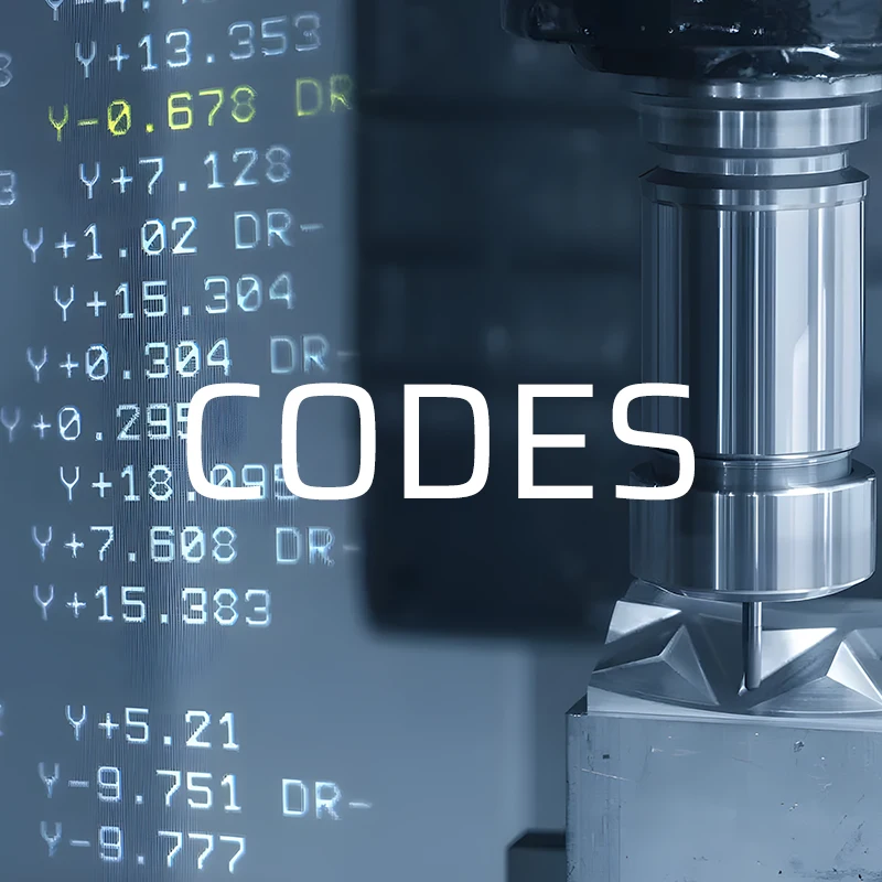
8 Common Mistakes in Machining and How to Avoid Them Read Post »

Scroll to Top