What is GD&T?
GD&T stands for Geometric Dimensioning and Tolerancing. It is a symbolic language used in engineering and manufacturing to precisely communicate the geometry and allowable variation (tolerances) of parts and assemblies.
Key Concepts in GD&T:
Geometric Tolerances: GD&T defines tolerances for form, orientation, location, and runout. These tolerances control the allowable variation in the shape and position of features on a part.
Feature Control Frames: These are rectangular boxes containing GD&T symbols, tolerance values, and datums that clearly communicate how much variation is allowed.
Datums: Reference points, lines, or surfaces on a part used to establish a coordinate system for measurement.
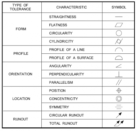
Symbols: GD&T uses standardized symbols (from ASME Y14.5 or ISO standards) to represent tolerances, such as:
Straightness (─)
Flatness (⏥)
Circularity (○)
Cylindricity (⌭)
Perpendicularity (⊥)
Parallelism (∥)
Position (⭘)
Concentricity (◎)
Symmetry (⌯)
Advantages of GD&T:
Improves communication between design, manufacturing, and inspection.
Reduces ambiguity compared to traditional dimensioning.
Allows for more cost-effective manufacturing by clarifying what is functionally important.
Example:
Imagine a hole in a plate. Instead of just giving its location and diameter with simple linear tolerances, GD&T can define:
The hole’s position tolerance relative to a coordinate system defined by datums.
Its cylindricity tolerance to control roundness and straightness along its axis.
Its perpendicularity to the surface.
This ensures the part functions as intended while allowing flexibility in manufacturing.
Why Implement GD&T Processes?
Great question! Implementing GD&T processes in design and manufacturing offers a bunch of important benefits that improve product quality, communication, and cost-efficiency. Here’s why companies and engineers choose to use GD&T:
1. Clear Communication of Design Intent
GD&T provides a standardized language that precisely defines allowable variation in part features.
This removes ambiguity compared to traditional dimensioning, reducing misinterpretations between design, manufacturing, and inspection teams.
2. Better Control Over Part Functionality
GD&T focuses on the function of a part rather than just its size.
By controlling geometric relationships (like flatness, perpendicularity, position), parts are more likely to assemble and function correctly, even if some dimensions vary within tolerances.
3. Improved Quality and Consistency
Using GD&T helps ensure parts meet critical requirements, reducing defects and rework.
Inspection becomes more straightforward and repeatable with clear tolerance zones tied to functional requirements.
4. Cost Savings
GD&T allows for functional tolerances instead of overly tight, uniform tolerances.
This flexibility can reduce manufacturing costs by allowing looser tolerances where acceptable without sacrificing quality.
It also decreases scrap rates and rework.
5. Simplified Inspection and Measurement
GD&T clearly defines how and where to measure features, speeding up inspection processes.
Using datums and feature control frames standardizes measurement setups.
6. Supports Advanced Manufacturing Techniques
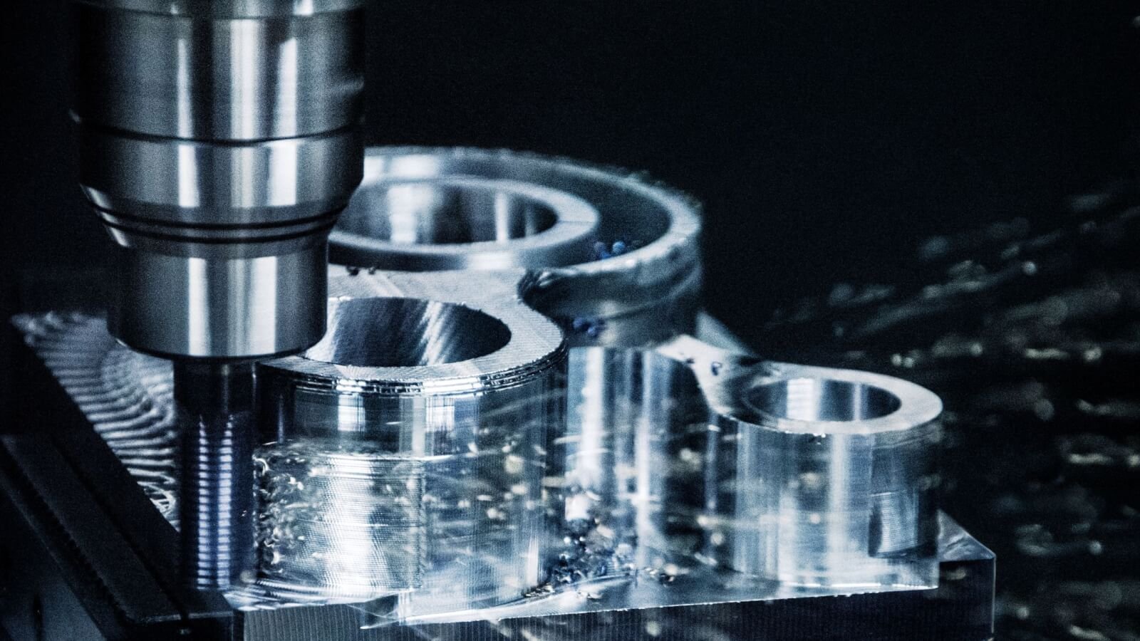
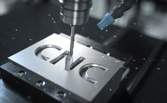
GD&T is essential for precision manufacturing methods, like CNC machining, 3D printing, and automated inspection.
It enables the use of coordinate measuring machines (CMMs) and software to verify complex geometries effectively.
7. Improved Interchangeability and Assembly
Ensures parts fit together properly even if manufactured by different suppliers.
Critical for large assemblies where multiple parts must interface precisely.
How GD&T Works
Defining the Part Geometry with Symbols
Instead of only specifying linear dimensions (like lengths or diameters), GD&T uses a set of standardized symbols to describe the form, orientation, location, and runout of features on a part. These symbols communicate what kind of geometric control is required.
Using Feature Control Frames
GD&T specifies tolerances in feature control frames—these are rectangular boxes attached to the drawing near a feature. A feature control frame contains:
The GD&T symbol (e.g., position, flatness)
The tolerance value (how much deviation is allowed)
Reference to datums (if applicable), which are the theoretical exact points or surfaces used as references for measurements
Establishing Datums
Datums serve as the “origin” or reference for measuring part features. GD&T sets up a coordinate system on the part using these datums, helping to define how features should be oriented or located relative to each other.
Tolerance Zones
GD&T defines tolerance zones where the feature must lie to be acceptable. For example:
A position tolerance creates a cylindrical zone within which the center of a hole must lie.
A flatness tolerance creates a zone between two parallel planes where a surface must lie.
Applying Functional Requirements
The tolerances set by GD&T are based on functional requirements—what the part needs to do, not just how big or small it should be. This makes sure the part works correctly in its assembly or operation.
Measuring and Inspecting
During inspection, the part is measured relative to the datums, and the measurements are compared to the tolerance zones specified by the GD&T. This helps ensure the part meets the required geometric standards.
Example in Practice:
Say you have a hole that must fit a pin tightly but still allow assembly:
Instead of just specifying a diameter tolerance, GD&T might specify a position tolerance with reference to the part’s edges (datums).
This controls not only the size but where the hole is located relative to the rest of the part, ensuring the pin fits properly.
GD&T Symbols
Form Controls
Flatness : This controls how flat a surface must be. The surface must lie between two parallel planes spaced apart by the tolerance value. It ensures no bumps or dips exceed the allowed flatness.
Straightness : Straightness controls how much a line or surface can deviate from a perfectly straight line. For example, the edge of a part or the axis of a cylindrical feature must be within a narrow straightness zone.
Circularity or Roundness: This ensures that any cross-section of a round feature (like a hole or shaft) is perfectly circular within a given tolerance. It prevents out-of-round conditions.
Cylindricity : A 3D form control that ensures a cylindrical feature is both round and straight along its entire length. It controls roundness, straightness, and taper simultaneously.
Orientation Controls
Perpendicularity : This controls the angle between a surface or feature axis and a datum plane or axis, ensuring it is exactly 90 degrees within a specified tolerance.
Parallelism : Parallelism makes sure that a surface or feature axis is parallel to a datum surface or axis, within the given tolerance.
Angularity: (not listed before, but part of GD&T) Controls the angle between a feature and a datum when it is something other than 90° or 0°.
Location Controls
Position : One of the most important GD&T symbols. It controls the exact location of a feature, like a hole or slot, within a defined tolerance zone relative to one or more datums. This ensures parts fit together correctly.
Concentricity : This ensures that the central axis of one cylindrical feature is aligned with the central axis of another datum feature, meaning their centers share the same axis.
Symmetry : Symmetry controls how a feature is positioned evenly on both sides of a central datum plane or axis, ensuring balanced placement.
Runout Controls
Circular Runout : This controls the variation of a surface as the part rotates around a datum axis. It’s often used on rotating shafts to limit wobble in any circular cross-section.
Total Runout : Similar to circular runout but applies to the entire surface along the axis of rotation, controlling variations in both straightness and roundness during rotation.
Each symbol corresponds to specific physical requirements for a part and is used on drawings within a feature control frame that defines the tolerance and datums to measure against. By using these controls, designers communicate precise requirements that ensure parts fit and function properly while allowing some manufacturing flexibility.
Limitations of Tolerancing Before GD&T
Before the widespread use of GD&T, tolerancing methods had several important limitations that often led to inefficiencies, misunderstandings, and increased costs in manufacturing and inspection processes. Here are some of the key limitations of traditional tolerancing before GD&T was implemented:
Ambiguity in Specifications: Traditional tolerancing relied heavily on linear dimensions and plus/minus values, which often didn’t clearly communicate the true functional requirements of a part. This ambiguity could lead to different interpretations by manufacturing and inspection teams.
Lack of Control Over Geometric Relationships: Simple dimensional tolerances focused mainly on size but didn’t effectively control the shape, orientation, or location of features. This sometimes resulted in parts that met size requirements but didn’t fit or function properly when assembled.
Overly Tight or Uniform Tolerances: Without the ability to specify functional geometric tolerances, designers often applied tight uniform tolerances to all features “just to be safe.” This increased manufacturing costs unnecessarily because machines had to hold tighter specs than required for proper function.
Inconsistent Inspection Methods: Traditional tolerances didn’t always provide clear guidance on how to inspect features, leading to inconsistent measurement techniques and results across different inspectors or facilities.
Poor Communication Between Teams: The lack of a standardized language meant designers, manufacturers, and quality inspectors often had to interpret drawings differently, which increased errors and rework.
Difficulty in Defining Datum References: Traditional tolerancing rarely specified clear reference points or datums for measurements, making it harder to consistently locate features and maintain assembly relationships.
Limited Support for Complex Shapes: As products became more complex, traditional dimensioning was inadequate for accurately specifying and controlling complex geometric forms and relationships.
Overall, before GD&T, tolerancing systems struggled to balance clear communication of design intent, functional requirements, and cost-effective manufacturing, leading to inefficiencies and higher rates of defective parts.
Conclusion
In conclusion, traditional tolerancing methods before the adoption of GD&T were often unclear, inconsistent, and limited in their ability to fully describe the functional requirements of parts. This led to miscommunication between design, manufacturing, and inspection teams, increased production costs due to unnecessarily tight tolerances, and difficulties in ensuring proper fit and function of assemblies. GD&T addressed these shortcomings by providing a standardized, precise, and functional language for defining geometric requirements, greatly improving product quality, communication, and manufacturing efficiency.
Related posts:
- 5-Axis Machining vs 3-Axis Machining – Essential Differences, Applications & Limitations
- Electrical Discharge Machining (EDM): Top 3 Types, Key Principles & Industries That Rely on It
- Laser Cutting vs. Waterjet Cutting: 7 Key Differences, Pros & Best Uses
- G-code and M-code Commands for CNC Beginners : 5 Essential & Effective Tips
- 3D Printing vs Machining: Powerful Comparison of Benefits, Limitations, and Applications
- How to Read Machining Drawings: 11 Essential Tips for Beginner