How to Read Machining Drawings?
Machining drawings are essential documents used in manufacturing and engineering to communicate detailed instructions for producing parts and assemblies. For beginners, reading and interpreting these drawings can be challenging but is a vital skill for machinists, engineers, and technicians. This guide will provide a comprehensive understanding of how to read machining drawings, step by step, including all necessary concepts, symbols, and practical advice.
1. Introduction to Machining Drawings
What Is a Machining Drawing?
A machining drawing, also known as a mechanical or engineering drawing, is a detailed, precise graphical representation of a part or assembly. It provides all the necessary information for manufacturing a component accurately.
The drawing uses a combination of:
Views to show different sides of the part
Dimensions to specify size
Tolerances to define acceptable variation
Symbols for features like holes, threads, and finishes
Notes for special instructions
Title blocks for administrative details
Why Are Machining Drawings Important?
Manufacturers rely on these drawings to create parts that fit together perfectly and perform their functions reliably. Any ambiguity or error can lead to defective products, wasted materials, and increased costs.
What You’ll Learn in This Guide
This guide will take you through the basic concepts, common symbols, dimensional specifications, and best practices to read and interpret machining drawings with confidence.
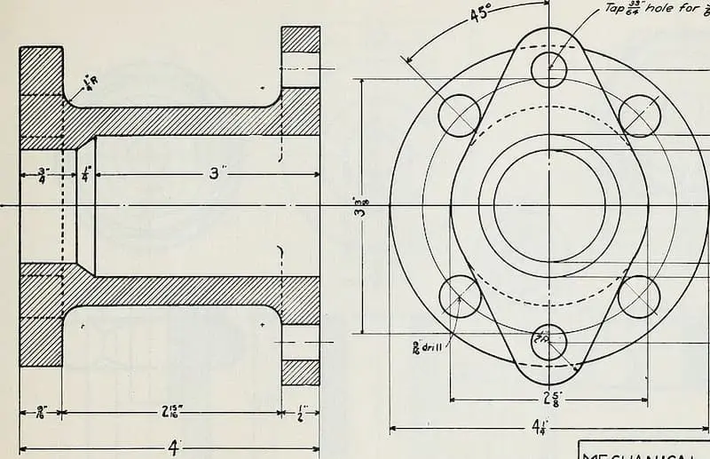
2. Understanding Views and Projections
One of the first challenges is to understand the views shown on a drawing, which represent a 3D object in 2D.
Orthographic Projection
Most machining drawings use orthographic projection to show different views of the part on flat planes. The most common are:
Front View: Shows the primary face of the part.
Top View: Shows the part as if looking down from above.
Side View: Shows the part from either the left or right side.
These views are aligned to help you mentally reconstruct the 3D shape.
How to Visualize the Part
Imagine the object inside a transparent box. Each face you look through corresponds to a view on the drawing.
For example, if the front view shows a rectangle with a hole in the center, and the top view shows the hole’s position along the length and width, you combine these to understand where the hole is located in the real part.
Additional Views
Isometric View: Sometimes included as a 3D representation, helps visualize the overall shape but is not used for precise measurement.
Section Views: Created by slicing the part along a plane to show hidden internal features.
Detail Views: Enlarged views of small or complex features for clarity.
3. Reading Dimensions and Units
Dimensions are crucial because they tell you the size of each feature.
Units of Measurement
Metric (millimeters) or Imperial (inches) units are used.
Units are usually indicated in the title block.
Always confirm which system is used to avoid costly mistakes.
Types of Dimensions
Linear dimensions: Lengths, widths, and heights.
Diameters: Shown with a Ø symbol.
Radii: Curved edges marked with an R.
Depth: Vertical extent of holes or pockets, indicated with a depth symbol (↧).
How Dimensions Are Shown
Dimensions are represented by lines with arrows at each end, pointing to the edges or features being measured. The measurement value is placed above or between the arrows.
Examples
50 mmmeans a length of 50 millimeters.Ø12.5 mmmeans a circular feature with a diameter of 12.5 mm.R5means a curve with a radius of 5 mm.
Reading Complex Dimensions
Some features might have multiple dimensions, such as:
Distance between holes
Size and location of slots
Angles between surfaces
4. Tolerances — The Allowable Variation
In manufacturing, exact dimensions cannot always be guaranteed. Tolerances define how much the actual measurement can differ from the nominal dimension.
Why Tolerances Matter
They balance cost and functionality. Tight tolerances increase manufacturing difficulty and cost but are necessary for precise parts.
Types of Tolerances
General tolerance: Applies to all dimensions if no specific tolerance is given.
Specific tolerance: Shown next to a particular dimension, e.g.,
25.00 ±0.05 mm.Limit tolerance: Two limits given instead of a nominal dimension plus/minus, e.g.,
24.95 mm - 25.05 mm.
Reading Tolerances on a Drawing
Look for tolerance notes in the title block or near the dimensions.
Understand what the numbers mean; for example,
±0.02means the actual size can vary by 0.02 mm above or below the nominal value.
Geometric Tolerances
In addition to size, drawings specify allowable variations in shape and position through Geometric Dimensioning and Tolerancing (GD&T) symbols.
Common geometric tolerances include:
Straightness
Flatness
Perpendicularity (⊥)
Parallelism (∥)
Position tolerance
Understanding these requires additional study, but the basic symbols will often appear on machining drawings.
5. Common Symbols and What They Mean
Symbols are shorthand for specific machining features and processes. Knowing them speeds up interpretation.
Hole and Thread Symbols
Ø – Diameter
Thread callout: e.g.,
M6 x 1means metric 6 mm diameter with 1 mm pitch.Counterbore: Symbol looks like a square bottomed hole.
Countersink: Symbol looks like a conical hole.
Surface Finish Symbols
Indicate how smooth the machined surface must be.
Shown as a checkmark-like symbol with numbers (e.g.,
Ra 1.6 µm).
Weld Symbols (If applicable)
Represent welding instructions, though more common on fabrication drawings.
Datum Symbols
Indicate reference points, lines, or surfaces for measurements.
6. Special Features in Machining Drawings
Machining drawings include detailed information about various features that must be created on the part. Understanding these features is essential for accurate manufacturing.
Holes are common features and come in several types:
Drilled holes are simple cylindrical openings.
Tapped holes are threaded to accept screws or bolts.
Reamed holes are precision holes finished to exact dimensions and smooth surfaces.
Hole specifications always include the diameter and often the depth. For threaded holes, the drawing specifies the thread size (such as M6 or 1/4-20) and the depth of the threaded portion.
Slots and grooves are cutouts that may be rectangular or curved. Their drawings provide dimensions such as length, width, and precise location relative to other features.
Chamfers and fillets modify edges:
A chamfer is an angled cut, often detailed with a note like “1×45°,” meaning a 1 mm length at a 45-degree angle.
A fillet is a rounded corner or edge, indicated by an R followed by the radius value (e.g., R5 means a 5 mm radius).
Threads are specified according to standards, like ISO metric for metric threads or UNC/UNF for imperial. Thread details include diameter, pitch (distance between threads), and length of thread engagement to ensure compatibility with mating parts.
Correct interpretation of these features ensures the part meets design requirements and functions as intended.
7. Title Block — Your Key Reference
Every machining drawing includes a title block, typically located in the bottom right corner of the sheet. The title block is a vital section because it contains key administrative and manufacturing information that helps identify and properly interpret the drawing.
What information is found in the title block?
Part Name and Number: This identifies the specific component or assembly the drawing represents. The part number is often used for ordering or inventory.
Drawing Number and Revision Status: The drawing number is a unique identifier for the document itself. The revision status (such as Rev A, Rev B) shows the current version of the drawing, indicating if it has been updated or modified.
Scale: This indicates the size relationship between the drawing and the actual part. For example, a scale of 1:2 means the drawing is half the size of the real component, while 2:1 means the drawing is twice as large.
Units: The units used for all dimensions, typically millimeters (mm) or inches, are clearly stated to avoid confusion.
Material Specifications: Details about the material to be used, such as aluminum 6061 or stainless steel, are often included here.
General Tolerances: Unless otherwise specified, these tolerances apply to all dimensions on the drawing.
Date and Drafter’s Name: This shows when the drawing was created and by whom, important for traceability.
Company Name and Logo: Identifies the organization responsible for the design.
8. Notes and Instructions
Machining drawings often include additional notes that provide important information beyond basic dimensions and tolerances. These notes are crucial for ensuring the part is manufactured and finished correctly according to design intent.
One common type of note covers heat treatment requirements. Heat treatment processes, such as hardening, tempering, or annealing, change the material properties like strength, hardness, and ductility. The drawing may specify the exact heat treatment cycle or temperature ranges required. Following these instructions ensures the part will perform as intended under operational conditions.
Another common set of notes relates to coatings or surface treatments. Examples include anodizing, plating, painting, or applying specialized finishes to improve corrosion resistance, wear resistance, or aesthetics. The drawing may specify the coating type, thickness, color, or standards to follow. These details are essential because they affect both appearance and durability.
Assembly instructions may also be included if the part is part of a larger assembly. These notes can cover how the part fits with others, alignment requirements, or special fastening instructions. Proper assembly ensures functionality and safety of the final product.
Some drawings specify special machining processes that are not routine. This might include processes like honing, grinding, electrical discharge machining (EDM), or laser cutting. Such instructions ensure the part meets tight tolerances or surface finish requirements that regular machining cannot achieve.
Because these notes often contain critical information impacting cost, quality, and performance, it is essential to read them carefully before starting production. Overlooking or misinterpreting notes can lead to manufacturing errors, delays, or part failures.
In summary, always pay close attention to the additional notes section on machining drawings—they are key to producing a part that meets all design and functional requirements.
9. Revision History
Machining drawings are living documents that often undergo changes as designs improve or errors are corrected. These updates are tracked in a dedicated section called the revision block or revision history, which records all changes made to the drawing over time.
Each revision is identified by a unique letter (like Rev A, Rev B) or number (Rev 1, Rev 2). This helps differentiate between versions and ensures everyone is working from the correct set of instructions.
Alongside each revision identifier, there is usually a brief note or description explaining what was changed. This might include updates to dimensions, added notes, corrections to errors, or changes in materials or tolerances. These notes help users understand the nature of the modifications without having to compare drawings side-by-side.
The revision block also includes the date when each revision was made and the name or initials of the person who approved the changes. This provides accountability and a clear record of who authorized the updates and when.
Using an outdated drawing revision can lead to significant manufacturing errors, wasted materials, and costly rework. Therefore, it’s crucial always to verify that you have the latest revision before starting any machining or inspection process.
Most companies have strict controls to manage revisions, often including revision numbers in the drawing file name or document control system. Always double-check the revision status, especially when receiving drawings from outside sources or when working on parts over an extended period.
In summary, understanding and tracking drawing revisions is essential for accuracy, quality, and communication in manufacturing. Always confirm you are referencing the most current version to avoid costly mistakes.
10. Practical Tips for Beginners
Start Simple
When you’re first learning to read machining drawings, begin with simple parts. Simple components typically have fewer features and clearer dimensions, making it easier to practice visualizing different views and understanding how dimensions relate to the part’s shape. Mastering simple drawings builds a strong foundation before moving on to complex parts.
Use Physical Models or CAD Software
A great way to improve your understanding is to use 3D models. Physical models let you hold and inspect the part from all angles, helping you connect the 2D drawing views to the actual shape. Alternatively, CAD software allows you to view, rotate, and zoom in on detailed digital models. This interactive approach helps build spatial awareness, which is key for interpreting complex drawings accurately.
Sketch the Part
Try sketching rough drawings based on the provided views. By manually drawing the front, top, and side views, you actively engage with the information. This practice helps you visualize the part in three dimensions and better understand the relationships between features like holes, slots, and chamfers. Sketching also reinforces your ability to interpret dimension lines and symbols.
Learn Standard Symbols and Terms
Machining drawings use many standardized symbols to represent features, tolerances, and surface finishes. Spend time learning these symbols and common terms. Keep a reference sheet or handbook handy as you work through drawings. Knowing these symbols saves time and reduces confusion.
Ask Questions
Never hesitate to ask questions if something on the drawing is unclear. Clarifying dimensions, notes, or symbols with engineers, designers, or supervisors helps prevent costly errors. A clear understanding ensures the part is manufactured correctly the first time.
By following these tips, you’ll steadily improve your ability to read and interpret machining drawings confidently.
11. Example Walkthrough
Let’s break down a simple machining drawing for a cylindrical part featuring a central hole. This example will help illustrate how to read basic views, dimensions, tolerances, and finish specifications.
Front View:
The front view depicts a cylinder standing upright. It shows that the part is 50 millimeters tall, with an overall diameter of 30 millimeters. This view gives you the height and the main outer dimension of the part.
Top View:
Looking down from above, the top view reveals the circular shape of the cylinder and importantly shows a central hole. This hole is positioned exactly in the middle of the circular face, confirming its location relative to the part’s outer diameter.
Hole Specifications:
The hole has a diameter of 10 millimeters, indicated by the symbol “Ø10 mm.” Its depth extends 25 millimeters into the cylinder, meaning it doesn’t go all the way through. The precise depth is crucial for the function of the hole, so this dimension must be followed exactly.
Tolerances:
The hole diameter comes with a tolerance of ±0.05 millimeters. This means the actual hole diameter can vary between 9.95 mm and 10.05 mm but must stay within these limits to ensure proper fit and function. Tolerances control how much variation is acceptable and are important for maintaining quality.
Surface Finish:
The drawing specifies a surface roughness value of Ra 1.6 micrometers on all external surfaces. This indicates how smooth the outer surfaces should be after machining, affecting the part’s appearance and how it interacts with other components.
Material:
The part is to be made from aluminum alloy 6061, a common material known for its strength and machinability.
Summary:
From this drawing, you understand that the part is a 30 mm diameter aluminum cylinder, 50 mm tall, with a precisely centered 10 mm diameter hole drilled 25 mm deep. The outer surfaces must be smoothly finished to a Ra 1.6 µm standard. This interpretation guides the machinist in producing the component exactly as required.
Related posts:
- Machining and Types of Machining.
- 5-Axis Machining vs 3-Axis Machining – Essential Differences, Applications & Limitations
- Electrical Discharge Machining (EDM): Top 3 Types, Key Principles & Industries That Rely on It
- Laser Cutting vs. Waterjet Cutting: 7 Key Differences, Pros & Best Uses
- 10 Must Have Machine Shop Tools Every Highly Efficient Workshop Needs
- 8 Common Mistakes in Machining and How to Avoid Them