
Forging Process may be defined as a metal working process by which metals or alloys are plastically deformed to the desired shapes by a compressive force applied with the help of a pair of dies. One die is stationary and other side in a linear motion. Forging process can be carried out both in cold and hot state of a metal. But unless otherwise mentioned, forging process is considered to be hot forging process.
Forging Designing Factors
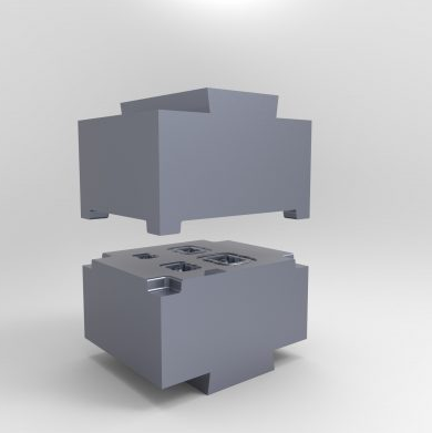
Part Geometry
Part geometry in forging refers to the shape, size, and design features of the component being forged. It encompasses all the physical characteristics—such as contours, thickness variations, fillets, corners, holes, and undercuts—that influence how the material flows during forging and how the die is designed. Proper consideration of part geometry is essential to ensure smooth metal flow, minimize defects, simplify die manufacturing, and achieve the desired mechanical properties and dimensional accuracy in the final forged product.
Purpose of Part Geometry
Ensures efficient and smooth metal flow during forging.
Minimizes the risk of defects like cracks, laps, and incomplete filling.
Helps maintain dimensional accuracy of the forged part.
Simplifies die design and manufacturing processes.
Extends die life by reducing excessive wear and stress.
Optimizes material usage and reduces waste.
Produces forged components with better mechanical properties and performance.
Ensures the final part meets required specifications and tolerances.
Factors Influencing Part Geometry
Material Type: Different metals and alloys have varying ductility and flow characteristics affecting geometry choices.
Complexity of Design: More intricate shapes may require special die features or multiple forging steps.
Thickness Variations: Sudden changes in thickness can cause uneven material flow and defects.
Fillet and Corner Radii: Proper rounding prevents stress concentrations and improves metal flow.
Draft Angles: Necessary for easy removal of the forged part from the die and to avoid sticking.
Size of the Part: Larger parts may need different design considerations to ensure complete filling and uniform flow.
Tolerance Requirements: Tighter tolerances require more precise geometry and often influence design decisions.
Type of Forging Process: Hot forging allows more complex geometries; cold forging demands simpler, more precise shapes.
Die Manufacturing Limitations: Some geometric features may be difficult or costly to machine into the die.
Intended Application and Load Conditions: Geometry must accommodate functional requirements like strength, fatigue resistance, and assembly fit.
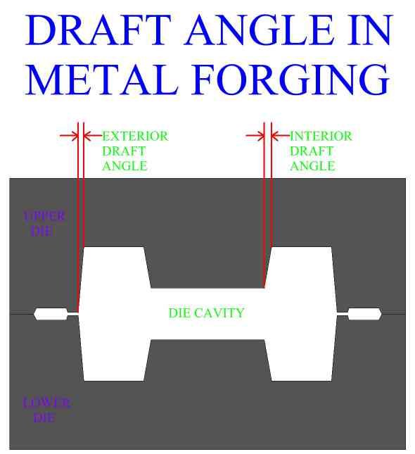
Draft Angle
A draft angle in forging refers to the taper provided on the vertical surfaces of a forged component or die cavity to facilitate the easy removal of the forged part from the die after deformation.
In hot forging, draft angles typically range from 3° to 7°, depending on factors such as the type of material being forged, the complexity of the part geometry, and the overall size of the component. The higher temperatures involved in hot forging allow for greater material deformation, but also require sufficient draft to ensure the forged part can be removed easily from the die without causing damage or excessive wear. In contrast, cold forging generally requires smaller draft angles, usually in the range of 0.5° to 2°. This is because cold forging operates at or near room temperature, where tighter dimensional tolerances are achievable and there is minimal thermal expansion. As a result, less draft is needed to maintain accuracy, but care must still be taken to allow smooth part ejection and avoid surface defects.
Purpose of Draft Angle
Prevents damage to both the die and the forged part during ejection.
Reduces the friction between the die and the workpiece.
Allows for smoother material flow during the forging process.
Factors Influencing Draft Angle
- Material type: Softer metals may require less draft, while harder or more ductile materials need more.
- Part geometry: Deep cavities or intricate shapes require larger draft angles.
- Surface finish requirements: Smaller draft may be used where a smoother finish or tighter dimensional control is needed.
- Die life and wear: Adequate draft angles reduce stress on die walls, extending die life.
Consequences of Inadequate Draft
Difficulty in ejecting the forged part.
Risk of die or part damage.
Increased wear and tear on die surfaces.
Potential defects in the forged product, such as drag marks or distortion.
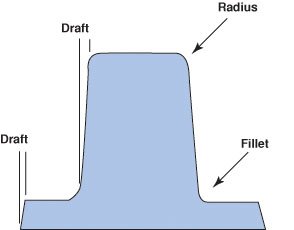
Fillet & Corner Radius
A fillet radius refers to the rounded internal corner where two surfaces of a forged part meet. It is designed to eliminate sharp transitions that can lead to stress concentrations and potential cracking during forging or in service. On the other hand, a corner radius is the rounded external edge or corner of a forged component. Like fillets, corner radii help promote smooth material flow, reduce die wear, and improve the overall strength and fatigue resistance of the part. Both fillet and corner radii are essential design elements in forging that contribute to part durability, dimensional accuracy, and manufacturing efficiency.
In hot forging, the material is heated to high temperatures, which significantly increases its ductility. This enhanced ductility allows for the use of larger fillet and corner radii, as the metal can flow more easily into the die cavities without excessive resistance. The larger radii also help reduce stress on the tooling and minimize the risk of cracks or defects during forming. In contrast, cold forging is performed at or near room temperature, where the material is less ductile and more resistant to deformation. As a result, smaller but still rounded radii are typically used to maintain tight dimensional tolerances and ensure precision. Even though the radii are smaller in cold forging, they are still necessary to facilitate metal flow and prevent sharp transitions that could lead to tool wear or part failure.
Purpose and Importance
Facilitates smooth material flow during deformation.
Reduces stress concentrations, minimizing the risk of cracking or failure.
Improves die life by reducing sharp transitions that cause excessive wear.
Enhances the structural integrity and fatigue resistance of the forged part.
Design Considerations
- Sharp corners are avoided to prevent metal flow restrictions and die damage.
- Rounded transitions help in maintaining consistent grain flow and better surface quality.
- Fillet and corner sizes should be optimized to balance formability, function, and tolerances.
Typical radius guidelines in forging are essential to ensure optimal material flow and structural integrity of the final part. For internal fillet radii, it is generally recommended to maintain a radius between 1.5 to 3 mm, although this can vary depending on the size of the part and the type of material being forged. This range helps prevent stress concentrations and supports consistent grain flow within the part. For external corner radii, the radius should be large enough to promote smooth metal flow during forging and to minimize die wear, yet not so large that it compromises the part’s fit or function in its final application. Properly selected fillet and corner radii contribute to better die life, improved forging quality, and enhanced mechanical performance of the forged component.
Result of Proper Design
- Better material flow
- Fewer defects in the final product
- Increased tool life
- Improved part quality and durability
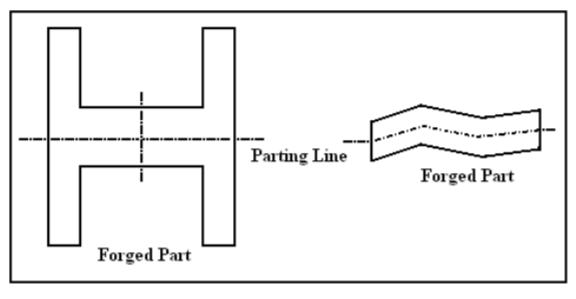
Parting Line
Parting line in forging is the line or surface formed where the two halves of a forging die come together and separate during the forging process. It represents the interface between the upper and lower die sections and is typically where the excess material, called flash, is squeezed out. The location of the parting line is critical because it influences metal flow, flash formation, ease of part removal, and overall dimensional accuracy of the forged component. Proper selection and design of the parting line help ensure efficient forging, minimize defects, and simplify downstream finishing operations.
Purpose and Importance
- Defines the interface between the two halves of the forging die.
- Allows separation of the die halves to remove the forged part after forming.
- Controls where excess material (flash) is formed and squeezed out during forging.
- Helps ensure proper metal flow by providing a clear split line for material displacement.
- Influences the ease of trimming and finishing by localizing flash.
- Affects dimensional accuracy and helps prevent defects like mismatch.
- Simplifies die design and manufacturing by establishing a consistent die closure plane.
- Enables efficient ejection and handling of the forged component after forming.
Design Considerations
Location at the Widest Section: Place the parting line at the largest cross-sectional area of the part to ensure proper metal flow and complete die filling.
Minimize Flash Formation: Position the line to control and limit flash, making it easier to remove without affecting part quality.
Avoid Critical Surfaces: Do not place the parting line on functional or critical surfaces to prevent flash marks or defects that require extensive finishing.
Ease of Die Manufacturing: Choose a parting line that simplifies die design and machining, reducing complexity and cost.
Facilitate Part Removal: Ensure the parting line allows easy ejection of the forged piece without causing damage or deformation.
Reduce Risk of Mismatch: Proper alignment and placement reduce the chances of mismatch defects at the parting line.
Consider Material Flow: The parting line should promote smooth metal flow to prevent defects such as laps or folds.
Symmetry and Balance: For symmetrical parts, position the parting line along the axis of symmetry for balanced forging and easier die setup.
Thermal Expansion: Account for die and material thermal expansion to avoid excessive gaps or tight spots at the parting line.
Flash and Gutter
Flash
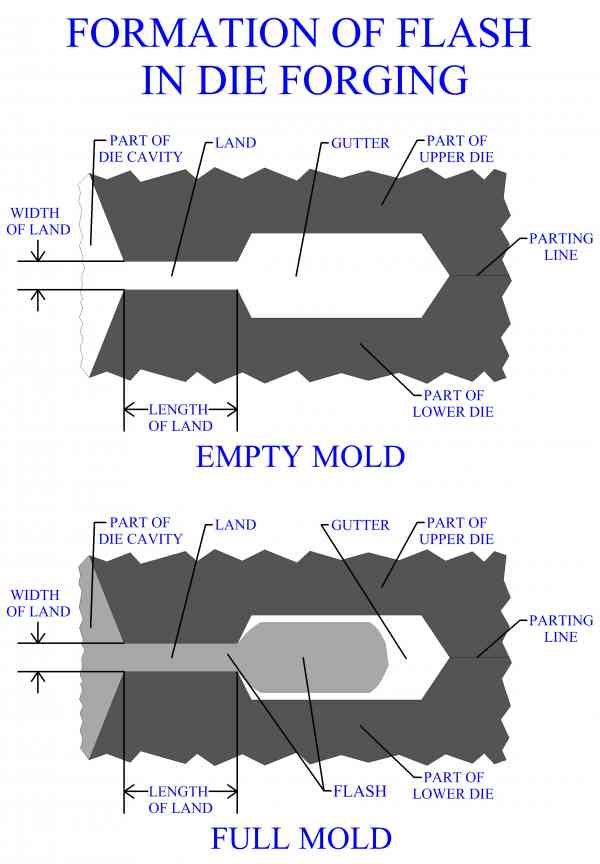
Flash is the thin excess material that flows out between the die halves during forging. It forms in a small gap known as the flash land.
Functions of Flash
Builds up pressure in the die cavity to ensure complete filling of complex shapes.
Acts as a pressure relief zone to prevent excessive force on the dies.
Assists in controlling material flow and reducing defects like underfilling.
Can help in dissipating heat (especially in hot forging).
Gutter
A gutter in forging is a specially designed cavity or recess located just outside the die impression, typically at the parting line, where excess material (flash) is collected during the forging process.
Functions of Gutter
1. Collect Excess Material (Flash)
After the die cavity is fully filled, the remaining material flows outward and forms flash.
The gutter provides a space to collect this flash, preventing it from interfering with the part shape or die closure.
2. Ensure Complete Die Filling
The flash and gutter system helps create backpressure, forcing the metal to completely fill fine details of the die cavity before escaping.
Without this, underfilling or incomplete forging can occur.
3. Control and Accommodate Material Flow
Gutters regulate the excess material to ensure consistent forging despite minor variations in billet size or shape.
They act as overflow zones.
4. Reduce Die Wear and Prevent Damage
By directing flash away from critical die areas, gutters minimize stress and thermal fatigue on the die edges.
Prevents flash from entering sealing surfaces, which could damage or misalign dies.
5. Aid in Post-Forging Operations
A well-designed gutter allows for easier trimming of flash.
Reduces manual or mechanical effort during flash removal.
Problems Caused by Poor Flash and Gutter Design in Forging
Poor design of the flash and gutter system in forging can lead to several serious issues. These problems affect product quality, material efficiency, and die life, and can result in increased costs and downtime.
1. Incomplete Die Filling
When the flash land is too short or narrow, it doesn’t generate enough backpressure to properly fill the die cavity. This leads to underfilling, especially in thin or complex areas of the forging.
Insufficient backpressure due to small flash land
Incomplete filling of intricate die sections
Risk of cold shuts and surface defects
2. Excessive Flash Formation
If the flash and gutter are oversized, too much material escapes the die cavity. This results in increased material waste and can disrupt the proper flow of metal.
Oversized flash land or gutter
Increased flash that needs trimming
Loss of dimensional accuracy
3. Die Wear and Fatigue
Poor flash design can cause concentrated stress and heat at the die edges. Over time, this leads to thermal fatigue, cracks, and accelerated die wear.
Flash too thick or poorly controlled
High stress on die parting surfaces
Reduced die life and more frequent replacements
4. Flash Intrusion into Die Cavity
If the sealing between dies is not tight due to poor flash/gutter design, flash may leak into unwanted areas, causing mismatches or parting line defects.
Flash enters sealing surfaces
Misaligned parts and poor surface finish
Possible damage to precision die features
5. Trimming Difficulties
Excessive or irregular flash is hard to remove and may require more effort or risk damaging the forged part during trimming.
Uneven or thick flash
Increased trimming time
Higher risk of trimming errors
6. Heat and Flow Imbalance
Flash acts as a heat sink. Poor flash design can lead to uneven heat distribution, making metal flow harder in some regions, especially in detailed parts.
Flash draws heat away from forging area
Risk of surface defects or folds
Poor forging consistency
7. Machine and Die Misalignment
Uneven or asymmetrical gutters can cause unbalanced forces during forging, which may lead to die shifting or misalignment.
Asymmetrical material flow
Die wear or shifting
Machine overload or vibration

